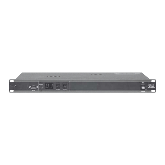
Summary of Contents for Alto MAXI-Q PC
- Page 1 User's Manual MAXI-Q PC 30+30 BAND DIGITAL EQUALIZER www.altoproaudio.com Version 1.1 August. 2005 English...
- Page 2 SAFETY RELATED SYMBOLS Fuse To prevent fire and damage to the product, use only the recommended fuse type as indicated in this CAUTION manual. Do not short-circuit the fuse holder. Before RISK OF ELECTRIC SHOCK DO NOT OPEN replacing the fuse, make sure that the product is OFF and disconnected from the AC outlet.
- Page 3 PREFACE Dear Customer: Thanks for choosing MAXI-Q PC 30+30 Band Digital Equalizer and thanks for choosing one of the results of AUDIO TEAM job and researches. For our LTO AUDIO TEAM, music and sound are more than a job...are first of all passion and let us say our obsession! We have been designing professional audio products for a long time in cooperation with some of the major brands in the world in the audio field.
-
Page 4: Table Of Contents
TABLE OF CONTENTS 1. INTRODUCTION ............................. 2. FEATURES ............................. 3. CONTROL ELEMENTS ......................... 3.1 The Front Panel 3.2 The Rear Panel 4. GETTING STARTED ..........................4.1 Configuration of the System 4.2 Memory Initialization 4.3 Firmware Update 4.4 Communication 5. REMOTE CONTROL .. -
Page 5: Introduction
1. INTRODUCTION Your MAXI-Q PC is a 30+30 Band Digital Equalizer and it also is a powerful versatile signal processor. you can set the input and output configuration only through recalling one of the presets included in the internal memory or PC Editor software. -
Page 6: The Rear Panel
7. AC inlet and fuse holder Use it to connect your MAXI-Q PC to the supplied AC cord. Please check the voltage in your country and what voltage for your MAXI-Q PC is configured before attempting to connect the unit for the main AC. The fuse can protect the AC supplies circuit of the equipment. -
Page 7: Memory Initialization
After finishing firmware update, you must restart the Maxi-Q PC to complete the update procedures. 4.4 Communication 1>.When the MAXI-Q PC is connected by its RS232 port to a PC running the MAXI-Q PC editor program, the display shows CG (Comm. Gateway). -
Page 8: How To Set The Maxi-Q Ps's Id Number
Run MAXIQ Editor program installed in your computer, then select NEW from the FILE menu, now fill out the right ID number of your MAXI-Q PC that is connected to the PC and press OK button, you will see the opening screen following (later software versions may differ). - Page 9 5.3.1 Main Page - Load Preset In this column of "Preset", you can select either a factory preset (1 ~ 10) or a user preset (1. ~ 128.), then press "Load Preset" button and the selected preset will be loaded. Factory Presets: they can be used normally, temporarily modified, but can't be cancelled, overwritten or permanently modified.
- Page 10 5.3.2 GEQ A/B 30 band Graphical EQ, it provides up to 24dB boost or cut at 30 frequency points (25Hz ~ 20KHz). The GEQ allows to alter the overall tone of the signal connected to the respective input. Click on one of the virtual level slider controls with your PC's left mouse button and hold the button down as you move the slider up or down.
-
Page 11: Connections
6. CONNECTIONS The following diagrams show the schemes of the recommended cables and some connection examples referred to various system configurations. Inputs A & B, RS485 IN GROUND BALANCED XLR-M HOT (+) COLD ( ) Inputs A & B SLEEVE GROUND BALANCED JACK RING... - Page 12 7. APPLICATION To operate one or more MAXI-Q PC units that are connected to a PC, you need to download a free Windows compatible MAXI-Q PC program from our website. To get a copy, please go to http://www.altomobile.com/html/support_forum.html and click "Data...
-
Page 13: Technical Specifications
8. TECHNICAL SPECIFICATIONS INPUT section Connectors 2 x COMBO Nominal input sensitivity 0 dB (0.775 V) Input Impedance 30kOhm, electronically balanced Maximum Input Level +20dBu Input Gain -30 / +6 dB variable in 0.5 dB steps 2 x XLR-M Output Section Connectors Output Impedance 600 Ohms, electronically balanced... -
Page 14: Warranty
9. WARRANTY 1. WARRANTY REGISTRATION CARD To obtain Warranty Service, the buyer should first fill out and return the enclosed Warranty Registration Card within 10 days of the Purchase Date. All the information presented in this Warranty Registration Card gives the manufacturer a better understanding of the sales status, so as to purport a more effective and efficient after-sales warranty service. - Page 15 No. 1, Lane 17, Sec. 2, Han Shi West Road, Taichung 40151, Taiwan http://www.altoproaudio.com Tel: 886-4-22313737 email: alto@altoproaudio.com Fax: 886-4-22346757 All rights reserved to ALTO. All features and content might be changed without prior notice. Any photocopy, translation, or reproduction of part of this manual without written permission is forbidden. Copyright 2005 SEIKAKU GROUP NF01972-1.1...


Need help?
Do you have a question about the MAXI-Q PC and is the answer not in the manual?
Questions and answers