
Related Manuals for FiveCo FMod-IPAXESCTRL

Summary of Contents for FiveCo FMod-IPAXESCTRL
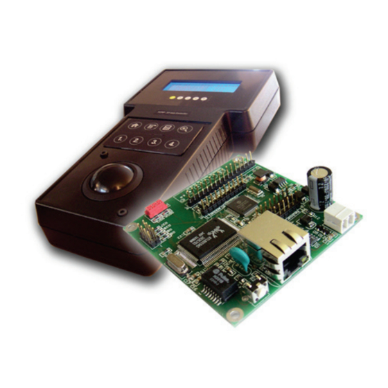
- Page 1 See page 9 for quick start 3 Axes Ethernet Control Board FMod-IPAXESCTRL User’s Manual Version 1.5...
- Page 2 Any failure of this device that may cause serious consequences should be prevented by implementation of backup systems. The user agrees that protection against consequences resulting from device system failure is the user's responsibility. Changes or modifications to this device not explicitly approved by FiveCo will void the user's authority to operate this device.
- Page 3 Same - Add checksum function example 27.01.06 - Correct function ID for easy change IP answer Same Same frame. 21.12.07 - New address Same Same 16.10.19 - Remove Java Applet and add new application. Same Same FMod-IPAXESCTRL User Manual v.1.5...
-
Page 4: Table Of Contents
Keyboard settings panel ..........................26 LCD text Panel ..............................24 Modes & Axes settings Panel ........................25 7. Reference zero absolute/relative ......................29 8. Registers management........................... 30 Memory Organization ........................... 30 Full Register Description ..........................31 FMod-IPAXESCTRL User Manual v.1.5... -
Page 5: Package And Operating Conditions
5 / 70 1. Package and operating conditions Package contents 1 Axes Ethernet Control board : FMod-IPAXESCTRL This manual (optional) Power Supply : Power over Ethernet IEEE802.3af Hub-injector (110-240 VAC, 50/60Hz -> +48v, 350 mA) Operating conditions ... -
Page 6: Overview
IEEE 802.3af standard which allows it to be powered through the Ethernet cable (PoE-Powered Device). The FMod-IPAXESCTRL board works without the use of a computer (PC or Mac). It communicates independently with the selected FMod-IPxxMOT devices (motor control cards) through the Ethernet network. -
Page 7: Connection Architecture (Ethernet)
(under an ADSL modem/router or a professional Router) and therefore make the system accessible from anywhere (remote). Note : It is also possible to connect the FMod-IPAXESCTRL directly to an FMod- IPxxMOT motor control card through a simple Ethernet Cross Cable (not using the switch). -
Page 8: Board Layout
8 / 70 Board Layout SOS button Power Power Ethernet RJ45 Keyboard 2x4 Keyboard 4x4 Trackball LEDs indicator LCD display 75.7 69.5 64.3 ∅3.2 70.5 Max height: 20mm FMod-IPAXESCTRL User Manual v.1.5... -
Page 9: Quick Start
The user agrees that protection against consequences resulting from device system failure is the user's responsibility. motion@fiveco.com / www.fiveco.com The MAC Address is the 48bits unique identifier on Ethernet networks. The IP Address can be modified. -
Page 10: Power And Network
Connect the cable to the card and to the PC Connection with an Ethernet crosscable 2. Connect a power supply (7-48V) or a POE injector to the module. Discrete power supply PoE with a Power injector FMod-IPAXESCTRL User Manual v.1.5... -
Page 11: Changing Ip Address
1. Plug your new card on your PC network. 2. Start the Win32 application. 3. Click on "File->Easy change IP address". 4. The software will scan the network and display a list of all FiveCo's devices found. 5. Select the MAC address corresponding to your new card. -
Page 12: Hardware
FMod-IPAXESCTRL, and is always ON. Different LCD colors are available, but FiveCo recommends Crystalfontz’ LCDs (www.crystalfontz.com) The LCD used by FiveCo is Crystalfontz’ model CFAH2004A-TMI-JP (with LSI HD44780 driver inside), blue-backlit with white characters (pictured on the left). FMod-IPAXESCTRL User Manual v.1.5... -
Page 13: Keyboard
13 / 70 The connector on the FMod-IPAXESCTRL board has the same pin configuration as the one of the LCD (allowing an easy flat-cable connection), but the LCD has to be used in 4bits data mode only. Board connector pinout:... -
Page 14: Trackball
(ex: Megatron model 816TC). Board J5 connector pinout and trackball connector pinout and axes: - (not connected) - (nc) - (nc) - (nc) Axe 1 FMod-IPAXESCTRL User Manual v.1.5... -
Page 15: Leds
15 / 70 LEDs The FMod-IPAXESCTRL is provided with a connector for 4 LED (J3). They give information about the mode (1, 2, 3) of the board and the state (activity or not) of the axes. Here is the LED’s layout:... -
Page 16: Sos Button
Do not use the “SOS IP address” as the normal IP for your module (during normal board operation). If you plug another module on the same network, both will have the same IP and will therefore be impossible to both configure. FMod-IPAXESCTRL User Manual v.1.5... -
Page 17: Tcp/Udp Server
The user can simply access that port and ask for a particular page, through the use of a standard Web browser, and typing the IP address of the card: Ex: type http://169.254.5.1/index.htm in the address bar of the browser and the “index.htm” page will be loaded. FMod-IPAXESCTRL User Manual v.1.5... -
Page 18: Tcp & Udp Control Port (# 8010)
The user defines himself the values of the Transaction ID. Normally, each packet/transaction (communication request) should have a different ID (even though this is not mandatory). When the FMod-IPAXESCTRL receives a command/packet, it sends back an answer (at each request). This answer contains the same Transaction ID than the corresponding command previously sent. - Page 19 The maximum number of registers that can be read at one time is almost 30. The answer sequence should not be greater than 180 bytes. If the number of registers is too high, the FMod-IPAXESCTRL will answer only with the value of some of them.
-
Page 20: Easy Ip Address Config (Udp # 7010)
IF NO TCP CONNECTION IS MADE TO THE BOARD. Byte# Number of bits Example 0x00 Change IP fct ack (0x002B) 16 bits 0x002B 0x02 TransactionID 16 bits 0x0000 0x04 Length of params (0x0000) 16 bits 0x0000 0x14 Checksum 16 bits 0x… FMod-IPAXESCTRL User Manual v.1.5... -
Page 21: Checksum Calculation
21 / 70 Checksum calculation This checksum is the same as the IP checksum. Definition: sum of 1’s complement of all 16 bits words of whole message (FiveCo packet) except checksum bytes. Note: all values are unsigned! Sequence: 1. Clear accumulator Loop x. - Page 22 Sum+= 0xFF; ChecksumCalculated = ((Sum>>16)&0xFFFF)+(Sum&0xFFFF); ChecksumCalculated = ((ChecksumCalculated>>16)&0xFFFF) +(ChecksumCalculated&0xFFFF); return ChecksumCalculated; This function needs a Byte array (ByteTab) containing the command sequence and the array’s length (Size) as input. It returns the checksum as an int. FMod-IPAXESCTRL User Manual v.1.5...
-
Page 23: Overview
: https://www.fiveco.ch/product-fmod-ipaxesctrl.html. Use the "Connection->Scan network" menu to scan the network to find the FMod-IPAXESCTRL you want to configure. If you have to change the IP address of the device, you can use the easy tool under "Connection- >Change IP Adress easily...". -
Page 24: Main Panel
The others panels allow to configure the device. Please note that you have to click on the "Change" button of the panel in which you made modifications to send them to the device (automatically saved in user EEPROM). HID Parameters Panel FMod-IPAXESCTRL User Manual v.1.5... -
Page 25: Modes & Axes Settings Panel
This panel allows management of the parameters of the 3 motor control boards [FMod-IPxxMOT] (IP address of each Axis) that can be controlled through the FMod-IPAXESCTRL card. For each axis, the user can define 3 DIFFERENT MODES that can be configured with different settings (HIDRatio/DiplayRatio). -
Page 26: Keyboard Settings Panel
Decrement axis 1 Decrement axis 1 in Mode 1 Increment axis 2 Increment axis 2 in Mode 1 Decrement axis 2 Decrement axis 2 in Mode 1 Increment axis 3 in Mode 1 Increment axis 3 FMod-IPAXESCTRL User Manual v.1.5... -
Page 27: Board's Communication Settings Panel
Function #23: If the press is short, "Go" is launched. If the button is pressed for more than 3 seconds, position 1 is saved. Other Parameters Panel This panel can be used to change the FMod-IPAXESCTRL board’s communication parameters (user should better use "Connection->Change IP Adress easily..." menu.): ... - Page 28 This panel allows also seeing the current input voltage of the power supply. Finally, if you want to reset all devices parameters to the factory state, click on the corresponding buttons. FMod-IPAXESCTRL User Manual v.1.5...
-
Page 29: Reference Zero Absolute/Relative
29 / 70 7. Reference zero absolute/relative FMod-IPAXESCTRL can work with the exact position coming from each FMod-IPxxMOT, in which case we speak about an absolute zero, because the “0” displayed on the FMod-IPAXESCTRL means that the corresponding axis POSITION register is really at position 0. -
Page 30: Registers Management
Action Number and description: SaveUserParameters (0x03) function During standard power-up or calling RestoreUserParameters (0x04) function RestoreFactoryParameters (0x05) function SaveFactoryParameters (0x06) function [For integrators engineers only] By pressing “SOS Button” after power-up By pressing “SOS Button” during power-up FMod-IPAXESCTRL User Manual v.1.5... -
Page 31: Full Register Description
0x29 (41) LCDMODE1TEXT 0x2A (42) LCDMODE2TEXT 0x2B (43) LCDMODE3TEXT Axis1 AXIS1POSITIONOFFSET 0x30 (48) 0x31 (49) AXIS1MACADDRESS AXIS1IPADDRESS 0x32 (50) 0x33 (51) AXIS1MODE1DISPLAYRATIO AXIS1MODE1HIDRATIO 0x34 (52) 0x35 (53) AXIS1MODE2DISPLAYRATIO AXIS1MODE2HIDRATIO 0x36 (54) 0x37 (55) AXIS1MODE3DISPLAYRATIO 0x38 (56) AXIS1MODE3HIDRATIO FMod-IPAXESCTRL User Manual v.1.5... - Page 32 0x46 (70) 0x47 (71) AXIS2MODE3DISPLAYRATIO 0x48 (72) AXIS2MODE3HIDRATIO Axis3 0x50 (80) AXIS3POSITIONOFFSET AXIS3MACADDRESS 0x51 (81) 0x52 (82) AXIS3IPADDRESS 0x53 (83) AXIS3MODE1DISPLAYRATIO 0x54 (84) AXIS3MODE1HIDRATIO 0x55 (85) AXIS3MODE2DISPLAYRATIO 0x56 (86) AXIS3MODE2HIDRATIO 0x57 (87) AXIS3MODE3DISPLAYRATIO AXIS3MODE3HIDRATIO 0x58 (88) FMod-IPAXESCTRL User Manual v.1.5...
- Page 33 It defines which kind of module it is. Normally, different TYPE modules are not software compatible. Example: Module with TYPE = 0x00040000 means Type=4 (4= IP axes controller), Model = 0. Limits: None Active: Each time the processor is running. FMod-IPAXESCTRL User Manual v.1.5...
- Page 34 Firmware 0x00010007 = Version 1, Revision 7 is compatible with all earlier revisions of the same version (ver 1.0 to 1.6) but might have new functionalities (which will be deactivated by default) or code optimizations. Limits: None Active: Each time the processor is running. FMod-IPAXESCTRL User Manual v.1.5...
- Page 35 Read/Write Control 0x02 RESETCPU Restart processor Write only Register Size Register structure Unit 0 Bytes none none Description: Restarts the CPU of the board. The communication will be lost. Active: Each time the processor is running. FMod-IPAXESCTRL User Manual v.1.5...
- Page 36 0x32 AXIS1IPADDRESS 0x58 AXIS3MODE3HIDRATIO 0x33 AXIS1MODE1DISPLAYRATIO 0x34 AXIS1MODE1HIDRATIO 0x35 AXIS1MODE2DISPLAYRATIO 0x36 AXIS1MODE2HIDRATIO 0x37 AXIS1MODE3DISPLAYRATIO 0x38 AXIS1MODE3HIDRATIO Limits: Do not change any of these parameters during 1 sec while saving! Active: Each time the processor is running. FMod-IPAXESCTRL User Manual v.1.5...
- Page 37 Read/Write Control Restores saved 0x04 RESTOREUSERPARAMETERS Write only values Register Size Register structure Unit 0 Bytes none none Description: Restores the user parameters from EEPROM. See SAVEUSERPARAMETERS (0x03) register list. Active: Each time the processor is running. FMod-IPAXESCTRL User Manual v.1.5...
- Page 38 Register structure Unit 0 Bytes none none Description: Restores factory parameters. See SAVEUSERPARAMETERS (0x03) register list. Active: Each time the processor is running SAVEUSERPARAMETERS must be performed after this function for next reboot to keep these parameters. FMod-IPAXESCTRL User Manual v.1.5...
- Page 39 EEPROM all configurable registers for both factory parameters and user parameters. Warning: This function also executes the SAVEUSERPARAMETERS function. See SAVEUSERPARAMETERS (0x03) saved register list. Limits: Do not change any of these parameters during 1 sec while saving! Active: Each time the processor is running. FMod-IPAXESCTRL User Manual v.1.5...
- Page 40 0x000000xx = 0.0 Step 0x000001xx = 0.004 Example: When read 0x00234567 = 2311527 , Voltage = 35.27 (2311527/65536) Information: Below effective 6.5 V (0x00068000), this value has no meaning. Active: Each time the processor is running. FMod-IPAXESCTRL User Manual v.1.5...
- Page 41 WARNING Bit to bit state Register Size Register structure Unit 4 Byte Unsigned Int 32 bits , each bit independent none Description: This register is reserved for future use. Active: Each time the processor is running, FMod-IPAXESCTRL User Manual v.1.5...
- Page 42 Bit to bit settings Write (Read) Register Size Register structure Unit 4 Byte Unsigned Int 32 bits , each bit independent none Description: This register is reserved for future use. Active: Each time the processor is running FMod-IPAXESCTRL User Manual v.1.5...
- Page 43 6 x Unsigned Byte none Description: Standard hardware unique identifier (world) for each device on an ethernet network. Information: If user writes into this register, the address will not be modified. This register is available only for information purposes. FMod-IPAXESCTRL User Manual v.1.5...
- Page 44 The module will change for a new IP address only when all of its communication ports are closed. Do not forget to run a SAVEUSERPARAMETERS command. Default value: 169.254.5.5 Example: For the IP=192.168.16.14 (0xC0, 0xA8, 0x10, 0x0E), write 0xC0A8100E to IPADDRESS. Active: Each time the processor is running. FMod-IPAXESCTRL User Manual v.1.5...
- Page 45 255.255.255.0 (Class C addresses) Default value: 255.255.0.0 Example: For the IP=10.2.6.45 and subnet mask = 255.255.0.0: IP address class = A netID = 10, subNetID = 2 and hostID = 6.45 Active: Each time the processor is running. FMod-IPAXESCTRL User Manual v.1.5...
- Page 46 4 communications will be blocked and the module will have to be reset! The timeout for each TCP/IP connection is reloaded when there is traffic through the port. Default value: Limitations: Max value: 255 Active: Each time the processor is running. FMod-IPAXESCTRL User Manual v.1.5...
- Page 47 Description: Name or description of the module. Example: For the name “Hello Module”; extend to 16 byte the name: “Hello Module”+5x space=16 Byte. So write 0x48656C6C 6F204D6F 64756C65 20202020. Active: Each time the processor is running. FMod-IPAXESCTRL User Manual v.1.5...
- Page 48 Register Size Register structure Unit 1 Byte Unsigned Int 8 bits none Description: Number of users connected to the card using TCP. Value can be 0 to 4. Active: Each time the processor is running. FMod-IPAXESCTRL User Manual v.1.5...
- Page 49 Bit to bit settings Write (Read) Register Size Register structure Unit 4 Byte Unsigned Int 32 bits , each bit independent none Description: This register is reserved for future use. Active: Each time the processor is running. FMod-IPAXESCTRL User Manual v.1.5...
- Page 50 Bit to bit settings Write (Read) Register Size Register structure Unit 4 Byte Unsigned Int 32 bits , each bit independent none Description: This register is reserved for future use. Active: Each time the processor is running. FMod-IPAXESCTRL User Manual v.1.5...
- Page 51 Bit to bit settings Write (Read) Register Size Register structure Unit 4 Byte Unsigned Int 32 bits , each bit independent none Description: This register is reserved for future use. Active: Each time the processor is running. FMod-IPAXESCTRL User Manual v.1.5...
- Page 52 Go / Save position 4 0x35 Go / Set position zero relative Note: All description with “/” have a different functionality if the key is pressed shortly (<3 seconds) or pressed for more than 3 seconds. FMod-IPAXESCTRL User Manual v.1.5...
- Page 53 With a 1 line and 4 columns Keyboard, with “Set all axes to Position mode” (0x01), increment (0x06), decrement Axis 1 (0x07) and “Go/Save position 1” (0x17) , write: 0x00000000000000000000000017070601 Active: Each time the processor is running. FMod-IPAXESCTRL User Manual v.1.5...
- Page 54 Each mode has a specific LCD display and a specific input/output ratio (input=HID/output=Display). Here is the list of registers selected with MODE=1: LCDMODE1TEXT 0x29 0x33 AXIS1MODE1DISPLAYRATIO AXIS1MODE1HIDRATIO 0x34 AXIS2MODE1DISPLAYRATIO 0x43 0x44 AXIS2MODE1HIDRATIO 0x43 AXIS3MODE1DISPLAYRATIO 0x44 AXIS3MODE1HIDRATIO Limits: Min: Max: Default: 1 (at power up) FMod-IPAXESCTRL User Manual v.1.5...
- Page 55 Typically at 25°C Vo is ~0.5V (Vdd-Vo=4.5v). Examples: 0-127 T°>25°C 128-255 T<25°C Limits: Min: ~2V (for 50°… 70°) Max: ~0V (for 0 … -20°C) Default: 127 = ~0.5V for 25° Active: Each time the processor is running. FMod-IPAXESCTRL User Manual v.1.5...
- Page 56 “2 ###’###’### pls __“ 40 … 59 “3####mm ###um (#) __“ 60 … 79 WARNING: Be sure to always send 20 characters for each line (4x), for a total of 80 characters (bytes) to this register. FMod-IPAXESCTRL User Manual v.1.5...
- Page 57 Write (Read) text Register Size Register structure Unit 80 Byte 80 x Char (Unsigned Byte) none Description: When register MODE=2, the text defined with LCDMODE2TEXT is displayed on the LCD. See LCDMODE1TEXT (0x29) for more details. FMod-IPAXESCTRL User Manual v.1.5...
- Page 58 Write (Read) text Register Size Register structure Unit 80 Byte 80 x Char (Unsigned Byte) none Description: When register MODE=3, the text defined with LCDMODE3TEXT is displayed on the LCD. See LCDMODE1TEXT (0x29) for more details. FMod-IPAXESCTRL User Manual v.1.5...
- Page 59 User-EEPROM. Limits: 0x7FFFFFFFF = 2’147’483’647 0x80000000 = -2’147’483’648 Default: Active: Each time the processor is running. To disable relative reference, write 0 or press Key with function “Set zero absolute”. FMod-IPAXESCTRL User Manual v.1.5...
- Page 60 6 Byte 6 x Unsigned Byte none Description: Standard ethernet network’s hardware unique identifier for axis number 1. Information: This register is available only for information purposes. Default: 0xFFFFFFFFFFFF while a connection has not already been made. FMod-IPAXESCTRL User Manual v.1.5...
- Page 61 Default: 169.254.5.5 (Axis 1) = default IP address of module FMod-IPDCMOT or FMod-IPECMOT. 169.254.5.6 (Axis 2) 169.254.5.7 (Axis 3) Example: For the IP=192.168.16.14 (0xC0, 0xA8, 0x10, 0x0E) , write 0xC0A8100E to AXIS1IPADDRESS. FMod-IPAXESCTRL User Manual v.1.5...
- Page 62 (integer value) is displayed on the corresponding axis line on the LCD. Default: Example: If you want to display micrometers (while MODE=1), and 1000 increments of axis 1 correspond to 1um, set AXIS1MODE1DISPLAYRATIO to 0.001 (1/1000). Active: Each time the processor is running, FMod-IPAXESCTRL User Manual v.1.5...
- Page 63 AXIS1MODE1HIDRATIO > 1. For small motor movement, multiple HID increments (a key pressed repetitively or several trackball pulses) can result in 1 position increments on the motor’s side. AXIS1MODE1HIDRATIO < 1. Active: Each time the processor is running, FMod-IPAXESCTRL User Manual v.1.5...
- Page 64 Register Name Function Read/Write Control Convert the 0x35 (53) AXIS1MODE2DISPLAYRATIO Write (Read) display value Register Size Register structure Unit 4 Byte Float 32 bits none Description: For MODE=2 and axis 1 only. See AXIS1MODE1DISPLAYRATIO (0x33) for details. FMod-IPAXESCTRL User Manual v.1.5...
- Page 65 Read/Write Control Convert human 0x36 (54) AXIS1MODE2HIDRATIO Write (Read) input to motor goal Register Size Register structure Unit 4 Byte Float 32 bits none Description: While MODE=2 only. For axis 1 only. See AXIS1MODE1HIDRATIO (0x34) for details. FMod-IPAXESCTRL User Manual v.1.5...
- Page 66 Function Read/Write Control Convert the 0x37 (55) AXIS1MODE3DISPLAYRATIO Write (Read) display value Register Size Register structure Unit 4 Byte Float 32 bits none Description: While MODE=3 only. For axis 1 only. See AXIS1MODE1DISPLAYRATIO (0x33) for details. FMod-IPAXESCTRL User Manual v.1.5...
- Page 67 Read/Write Control Convert human 0x38 (56) AXIS1MODE3HIDRATIO Write (Read) input to motor goal Register Size Register structure Unit 4 Byte Float 32 bits none Description: While MODE=3 only. For axis 1only. See AXIS1MODE1HIDRATIO (0x34) for details. FMod-IPAXESCTRL User Manual v.1.5...
- Page 68 0x40 – 0x48 All Axis 2 registers 0x30 – 0x38 The use of these registers (0x40-0x48) is the same as described for AXIS 1, but applied to AXIS 2. Please refer to the corresponding pages in this manual. FMod-IPAXESCTRL User Manual v.1.5...
- Page 69 0x50 – 0x58 All Axis 3 registers 0x30 – 0x38 The use of these registers (0x50-0x58) is the same as described for AXIS 1, but applied to AXIS 3. Please refer to the corresponding pages in this manual. FMod-IPAXESCTRL User Manual v.1.5...
- Page 70 70 / 70 Contact address: FiveCo - Innovative Engineering En Budron H11 CH-1052 Le Mont-sur-Lausanne Switzerland Tel: +41 21 632 60 10 Fax: +41 21 632 60 11 www.fiveco.ch info@fiveco.ch FMod-IPAXESCTRL User Manual v.1.5...
Need help?
Do you have a question about the FMod-IPAXESCTRL and is the answer not in the manual?
Questions and answers