Siemens Simatic IPC520A Operating Instructions Manual
Industrial pc
Hide thumbs
Also See for Simatic IPC520A:
- Quick install manual (2 pages) ,
- Quick start manual (2 pages)
Table of Contents
Advertisement
SIMATIC IPC520A
SIMATIC
Industrial PC
SIMATIC IPC520A
Operating Instructions
11/2021
A5E51366325-AA
Preface
Overview
Safety instructions
Installing and connecting
the device
Installing OS and SDK
components
Expanding the device
Maintaining and repairing
the device
Technical specifications
Technical support
Digital I/O terminal block
Markings and symbols
List of abbreviations
1
2
3
4
5
6
7
A
B
C
D
Advertisement
Table of Contents

Related Manuals for Siemens Simatic IPC520A


Summary of Contents for Siemens Simatic IPC520A
- Page 1 SIMATIC IPC520A Preface Overview SIMATIC Safety instructions Installing and connecting the device Industrial PC SIMATIC IPC520A Installing OS and SDK components Expanding the device Operating Instructions Maintaining and repairing the device Technical specifications Technical support Digital I/O terminal block Markings and symbols...
- Page 2 Note the following: WARNING Siemens products may only be used for the applications described in the catalog and in the relevant technical documentation. If products and components from other manufacturers are used, these must be recommended or approved by Siemens. Proper transport, storage, installation, assembly, commissioning, operation and maintenance are required to ensure that the products operate safely and without any problems.
-
Page 3: Preface
• SIMATIC IPC520A Quick Install Guide • SIMATIC IPC520A Operating Instructions Conventions The term "device" is sometimes used to refer to the SIMATIC IPC520A in this documentation. Figures This manual contains figures of the described devices. The supplied device may differ in some details from the figures. -
Page 5: Table Of Contents
Connecting the power supply ..................... 32 Installing OS and SDK components ..................... 33 Flashing the Ubuntu Operating System ................33 Installing the "Siemens IPC520A support package" .............. 37 Documentation for "Siemens IPC520A support package" ............. 37 Expanding the device .......................... 39 Installing the M.2 module .................... - Page 6 Digital I/O terminal block ........................71 Markings and symbols ......................... 73 Overview ........................... 73 Safety ..........................73 Operator controls ......................73 Certificates, approvals and markings .................. 74 Interfaces .......................... 75 List of abbreviations ..........................77 Index ..............................79 SIMATIC IPC520A Operating Instructions, 11/2021, A5E51366325-AA...
- Page 7 Table of contents SIMATIC IPC520A Operating Instructions, 11/2021, A5E51366325-AA...
-
Page 9: Overview
Overview Product description Features SIMATIC IPC520A is powered by NVIDIA® Jetson™ Xavier NX module. It provides high-level industrial functionality, accelerated AI performance to the Edge in a power-efficient and compact form factor. • Compact design • Fanless • Vibration control performance •... -
Page 10: Structure Of The Devices
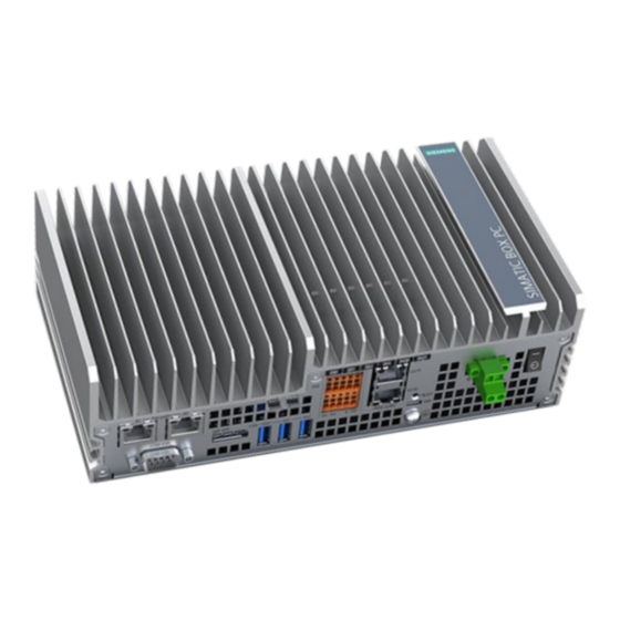
The front view on the left is the standard mounting position. The side view is on the right. ① Cooling fins ② LED display Top view ① Vent holes ② Antenna slot ③ Micro SD/ Nano SIM card slot SIMATIC IPC520A Operating Instructions, 11/2021, A5E51366325-AA... -
Page 11: Interfaces Of The Device
1 × USB 2.0 Micro B port ⑧ RESET button Reset the device to factory settings ⑨ Power supply (X80) Connection for a 24 V DC power supply ⑩ On/Off button Switch on (position "一"); Switch off (position " ") SIMATIC IPC520A Operating Instructions, 11/2021, A5E51366325-AA... -
Page 12: Status Displays
System sleep USER Off/Red/Green/Orange Customize Accessories Accessories from Siemens are available for your device. These are not included in the scope of delivery. Additional accessories can be found on the Internet: • Industry mall ((https://mall.industry.siemens.com/)) • Expansion components and accessories (https://new.siemens.com/global/en/products/automation/pc-based.html) - Page 13 Overview 1.3 Accessories Mounting accessory kit The mounting accessory kit contains: • One standard rail bracket ① • Two wall mounting brackets ② • One DC connecting terminal block ③ • Eight M3 screws SIMATIC IPC520A Operating Instructions, 11/2021, A5E51366325-AA...
-
Page 15: Safety Instructions
WARNING Risk of fire through expansion cards Expansion cards generate additional heat. The device may overheat and cause a fire. Note the following: • Observe the safety and installation instructions for the expansion cards. SIMATIC IPC520A Operating Instructions, 11/2021, A5E51366325-AA... - Page 16 LEDs on a plug-in card in the device visible. • Cables are routed from the inside out of the device or from the outside into the device, for example, to connect sensors or displays. SIMATIC IPC520A Operating Instructions, 11/2021, A5E51366325-AA...
- Page 17 When you touch electrostatic sensitive components, you can destroy them through voltages that are far below the human perception threshold. If you work with components that can be destroyed by electrostatic discharge, observe the ESD Guideline. SIMATIC IPC520A Operating Instructions, 11/2021, A5E51366325-AA...
-
Page 18: Security Information
Siemens' products and solutions undergo continuous development to make them more secure. Siemens strongly recommends that product updates are applied as soon as they are available and that the latest product versions are used. Use of product versions that are no longer supported, and failure to apply the latest updates may increase customers' exposure to cyber threats. -
Page 19: Notes On Use
This device is designed for use in a normal industrial environment according to IEC 60721-3- Security notification Siemens recommends that you observe the following security practices: • Enable secure boot feature to the first stage of boot/Cboot/kernel/DTB to prevent attack. - Page 20 Safety instructions 2.5 Notes on use SIMATIC IPC520A Operating Instructions, 11/2021, A5E51366325-AA...
-
Page 21: Installing And Connecting The Device
5. Check the contents of the packaging and any accessories you may have ordered for completeness and damage. – Device – One mounting accessory kit includes: one DC connecting terminal block, one standard rail bracket, two wall mounting brackets and eight screws. SIMATIC IPC520A Operating Instructions, 11/2021, A5E51366325-AA... -
Page 22: Identification Data Of The Device
You can find this information on the rating plate. The following illustration shows an example. Enter the identification data in the table below: Order number 6ES7647-0JB00-0YA2 Serial number Production version All existing Ethernet addresses (MAC) SIMATIC IPC520A Operating Instructions, 11/2021, A5E51366325-AA... -
Page 23: Permitted Mounting Positions And Mounting Types
Installing and connecting the device 3.1 Preparing for installation The following image shows the product label on the SIMATIC IPC520A as an example. 3.1.3 Permitted mounting positions and mounting types The device can be mounted horizontally on a DIN rail or to a wall. -
Page 24: Mounting The Device
• This device is designed for use in a normal industrial environment. Without additional protective measures (such as the provision of clean air), SIMATIC Box PCs may not be operated in harsh environments that are subject to caustic vapors or gases. SIMATIC IPC520A Operating Instructions, 11/2021, A5E51366325-AA... - Page 25 If you use anchors and screws other than those specified in the following table for wall mounting, safe mounting is not guaranteed. The device can fall and may be damaged. Only use the anchors and screws specified in the following table. SIMATIC IPC520A Operating Instructions, 11/2021, A5E51366325-AA...
- Page 26 This can result in personal injuries or material damage. Ensure that the wall is capable of bearing four times the total weight of the device (including the brackets and expansion modules). The total weight of the device is approximately 2 kg. SIMATIC IPC520A Operating Instructions, 11/2021, A5E51366325-AA...
-
Page 27: Mounting On Din Rails
Mounting on a standard rail is suitable for horizontal and vertical mounting of the device. Requirements • A SIEMENS 35 mm standard rail TH35-15 conforming to EN 60715:200 is mounted. • A standard rail bracket The standard rail bracket and two screws are included in the order variant "Standard rail mounting". -
Page 28: Wall Mounting
Secure each of the mounting bracket with 2 screws. Place the device with the mounting brackets onto the mounting surface. Mark the fixing holes. Drill the fixing holes. Insert the anchors in the drilled holes. Screw on the device. SIMATIC IPC520A Operating Instructions, 11/2021, A5E51366325-AA... -
Page 29: Connecting The Device
• Only connect I/O devices which are approved for industrial applications in accordance with EN 61000-6-2 and IEC 61000-6-2. • I/O devices that are not hot-pluggable may only be connected after the device has been disconnected from the power supply. SIMATIC IPC520A Operating Instructions, 11/2021, A5E51366325-AA... - Page 30 The interference immunity of the device according to the data in the technical specifications is only guaranteed when the cables at USB and micro USB ports are equipped with a ferrite magnet. Only use USB cables equipped with a ferrite magnet. SIMATIC IPC520A Operating Instructions, 11/2021, A5E51366325-AA...
-
Page 31: Connecting The Protective Conductor
M4 thread with the torque of 1.5 Nm (see part labeled). Connect the protective conductor to the protective conductor connection of the cabinet or the plant in which the device is installed. SIMATIC IPC520A Operating Instructions, 11/2021, A5E51366325-AA... -
Page 32: Connecting The Power Supply
• Tightening torque: 0.56 Nm • A slotted screwdriver with a 3 mm blade. Procedure Switch off the 24 V DC power supply. Connect the wires of the power supply. Connect the connection terminal at the marked position. SIMATIC IPC520A Operating Instructions, 11/2021, A5E51366325-AA... -
Page 33: Installing Os And Sdk Components
Bus <xxx> Device <xxx>: ID 0955: <7e19> Nvidia Corp Otherwise, redo the step 2. 3. Start up NVIDIA SDK Manager, and register an NVIDIA account to log in to NVIDIA SDK Manager. SIMATIC IPC520A Operating Instructions, 11/2021, A5E51366325-AA... - Page 34 NVIDIA website. (https://docs.nvidia.com/sdk-manager/install-with- sdkm-jetson/index.html) – STEP 01 DEVELOPMENT ENVIRONMENT: Select “Jetson Xavier NX modules" as the Target Hardware. Select “JetPack4.6” or later versions as the Linux version and then click "CONTINUE" button. SIMATIC IPC520A Operating Instructions, 11/2021, A5E51366325-AA...
- Page 35 Select “Jetson Xavier NX" radio button and click "OK" button in the pop-up window. – STEP 02 DETAIL AND LICENSE: For “TARGET COMOINTENTS”, click the checkbox before “Jetson OS”; and for “Jetson SDK Components”, select the required components as your need. SIMATIC IPC520A Operating Instructions, 11/2021, A5E51366325-AA...
- Page 36 Only if the status of Flash Jetson OS is “Success”, the flashing is successful, and you can ignore errors if there's any in the status. 5. Press the on/off button to switch off IPC520A, then press the button again to switch it on. SIMATIC IPC520A Operating Instructions, 11/2021, A5E51366325-AA...
-
Page 37: Installing The "Siemens Ipc520A Support Package
2. Search the "Siemens IPC520A support package" in the Siemens Industry Online Support website (https://support.industry.siemens.com/cs/ww/en/view/75852684)and download it on the USB stick whose file format is FAT/FAT32. 3. Copy the "Siemens IPC520A support package" from the USB stick to the IPC520A and enter the following command: $ sudo dpkg --force-overwrite -i ipc520a-${VERSION}_arm64.deb Note: {VERSION} must be the latest version. - Page 38 Installing OS and SDK components 4.3 Documentation for "Siemens IPC520A support package" SIMATIC IPC520A Operating Instructions, 11/2021, A5E51366325-AA...
-
Page 39: Expanding The Device
Installing the M.2 module Introduction to the M.2 module Siemens uses the M.2 module to extend the Siemens IPC. You can use M.2 module produced by Siemens or other third-party suppliers. Our device provides two M.2 Key B/ Key E interfaces and mounting positions. - Page 40 Use a screwdriver to pry open the reserved antenna holes. Make sure that there are no iron scraps left on the motherboard. Procedure - Removing the M.2 module Follow the above steps in reverse order to remove the M.2 module. SIMATIC IPC520A Operating Instructions, 11/2021, A5E51366325-AA...
-
Page 41: Inserting The Micro Sd Card/Nano Sim Card
Open the card cover on the bottom. Push the Micro SD card/Nano SIM card correctly into the supporting frame. The contacts of the Micro SD card/Nano SIM card must face to the motherboard. Push the card cover back. SIMATIC IPC520A Operating Instructions, 11/2021, A5E51366325-AA... - Page 42 Expanding the device 5.2 Inserting the Micro SD card/Nano SIM card SIMATIC IPC520A Operating Instructions, 11/2021, A5E51366325-AA...
-
Page 43: Maintaining And Repairing The Device
Maintaining and repairing the device Maintenance To maintain high system availability, Siemens recommends preventative replacement of the back-up battery at replacement intervals of 3 years. Repair information Carrying out repairs Only qualified personnel are permitted to repair the device. Contact your local representative, see section "Service and support (Page 69)". -
Page 44: Replacing The Backup Battery
– Rated voltage: 3 V DC – Max abnormal charging current: 10 mA • For any requirements on product maintenance, contact Siemens Technical support (Page 69). • Do not throw lithium batteries into fire, do not solder on the cell body, do not recharge, do not open, do not short-circuit, do not reverse polarity, do not heat above 100°C and... - Page 45 – Courant de charge anormal max. : 10 mA • Pour toute demande concernant la maintenance du produit, contactez le support technique (Page 69) Siemens. • Ne jetez pas au feu des piles au lithium, n'effectuez pas de soudage sur la pile, ne la rechargez pas, ne l'ouvrez pas, ne la court-circuitez pas, n'intervertissez pas les pôles, ne...
-
Page 46: Recycling And Disposal
Contact a certified disposal service company for electronic scrap for environmentally sound recycling and disposal of your old devices, and dispose of the device according to the relevant regulations in your country. SIMATIC IPC520A Operating Instructions, 11/2021, A5E51366325-AA... -
Page 47: Technical Specifications
EU L96, 29/03/2014, p. 357–374 (from 20.04.2016) EN 61000-6-2, EN 61000-6-4; ISO 9001 certificate The Siemens quality management system for all production processes (Development, Production, Sales and Service of Automation Products, -Systems and -Solutions) meets the requirements of ISO 9001:2015 Certificate registration no. -
Page 48: Directives And Declarations
The following abbreviations are commonly used for electrostatic sensitive devices: • ESD – Electrostatic sensitive device • ESD – Electrostatic Sensitive Device as a common international designation Electrostatic sensitive devices can be labeled with an appropriate symbol. SIMATIC IPC520A Operating Instructions, 11/2021, A5E51366325-AA... - Page 49 These values conform to the specifications of IEC 61000-4-2. ① Synthetic materials ② Wool ③ Antistatic materials such as wood or concrete SIMATIC IPC520A Operating Instructions, 11/2021, A5E51366325-AA...
- Page 50 This way, the discharge energy does not reach and damage the sensitive components. – Discharge your body electrostatically before you take a measurement at a module. Do so by touching grounded metallic parts. Always use grounded measuring instruments. SIMATIC IPC520A Operating Instructions, 11/2021, A5E51366325-AA...
-
Page 51: Dimension Drawings
Technical specifications 7.3 Dimension drawings Dimension drawings Wall mounting All dimensions in mm. SIMATIC IPC520A Operating Instructions, 11/2021, A5E51366325-AA... - Page 52 Technical specifications 7.3 Dimension drawings Mounting on a standard rail All dimensions in mm. SIMATIC IPC520A Operating Instructions, 11/2021, A5E51366325-AA...
-
Page 53: General Technical Specifications
61000-4-5; Length of signal port extension cable ≥ 30 m Immunity to discharges of static ± 4 kV contact discharge in accordance with IEC 61000-4-2 electricity ± 8 kV air discharge in accordance with IEC 61000-4-2 SIMATIC IPC520A Operating Instructions, 11/2021, A5E51366325-AA... - Page 54 RS232, max. 115 Kbps, D-sub connector, 9-pin • RS422, max. 115 Kbps, D-sub connector, 9-pin • RS485, max. 115 Kbps, D-sub connector, 9-pin Digital I/O Connector (X10) • 4 × DI + 2 × DQ SIMATIC IPC520A Operating Instructions, 11/2021, A5E51366325-AA...
-
Page 55: Ambient Conditions
10 to 58 Hz: 0.0375 mm • 58 to 200 Hz: 4.9 m/s² Storage/transport • 5 to 8.4 Hz: 3.5 mm • 8.4 to 500 Hz: 9.8 m/s Shock resistance, tested in accordance with IEC 60068-2-27 SIMATIC IPC520A Operating Instructions, 11/2021, A5E51366325-AA... -
Page 56: Power Demand Of The Components
Power consumption (at a rated voltage of 24 V) Basic device 20 W POE max. load 2 × 15 W or 1 × 30 W USB port max. load 6.5 W Xavier NX modules 15 W SIMATIC IPC520A Operating Instructions, 11/2021, A5E51366325-AA... -
Page 57: Hardware Descriptions
Technical specifications 7.8 Hardware descriptions Hardware descriptions 7.8.1 Motherboard The following figures show the motherboard of the SIMATIC IPC520A. Component/interface Description Meaning H1100 Power (green) H1101 User User LED (green/red/orange), programmable H1200, H1201, H1202, LEDs DI0, DI1, DI2, DI3 Input insert (Green) -
Page 58: External Interfaces
• 4 × DI + 2 × DQ (X10) 7.8.2.2 Power supply Plug connector, 2-pin Name of interface on the device: X1080 Assignment GND (M) DC 24 V (19.2 to 28.8 V DC) (L+) SIMATIC IPC520A Operating Instructions, 11/2021, A5E51366325-AA... -
Page 59: Digital I/O Connector
Logic 0 signal (max.) 5 V±2V DC at 1 mA Isolation (field side to logic) 500 V AC for 1 minute Input frequency • Normal input • Max. 20 Hz • High speed input • SIMATIC IPC520A Operating Instructions, 11/2021, A5E51366325-AA... - Page 60 10 Hz Resistive load/lamp load 10 Hz Inductive load 0.5 Hz Wiring diagrams Digital I/O connector uses a double-level terminal block for connection. For more information, refer to Digital I/O terminal block (Page 71). SIMATIC IPC520A Operating Instructions, 11/2021, A5E51366325-AA...
-
Page 61: Usb
Data channel USB3 Input Ground – Data channel USB3 Output Data channel USB3 Output USB 2.0 Micro B Name of interface on the device: X64 Assignment +5 V DC, out (max. 500 mA) USB-DN USB-DP SIMATIC IPC520A Operating Instructions, 11/2021, A5E51366325-AA... -
Page 62: Displayport
Auxiliary channel+ Bidirectional Ground AUX_CH- Auxiliary channel- Bidirectional Hot Plug Detect Input Ground DP_PWR +3.3 V (Power switch) power out 7.8.2.6 Ethernet port RJ45 socket Name of interface on the device: X1P1--PoE(LAN)--X2P1; X3P1; X3P2 SIMATIC IPC520A Operating Instructions, 11/2021, A5E51366325-AA... -
Page 63: Serial Port
RS 485 Assignment RS 232 Short description Meaning Data carrier detect (I) Received data (I) Transmitted data (O) Ground Data set ready (I) Request to send (O) Clear to send (I) Incoming call (I) SIMATIC IPC520A Operating Instructions, 11/2021, A5E51366325-AA... -
Page 64: Internal Interfaces
1 × Micro SD slot Nano SIM card slot Internal 1 × SIM card slot (X90) M.2 Key E (X100) Internal Support WiFi/BT card through PCIe ×1/USB2.0 M.2 Key B (X101) Internal Support WWAN card through PCIe ×1/USB3.0 SIMATIC IPC520A Operating Instructions, 11/2021, A5E51366325-AA... -
Page 65: Micro Sd Interface
3.3V 3.3V SUSCLK RESET# SIM DETECT ANTCTL3 COEX_RXD(I) ANTCTL2 COEX_TXD(O) ANTCTL1 COEX3(I/O) ANTCTL0 REFCLKp PEWAKE# REFCLKn CLKREQ# PERST# PETp0 PETn0 ALERT# PERp0 SMB_DATA PERn0 SMB_CLK DEVSLP PETp1 UIM-PWR PETn1 UIM-DATA UIM-CLK PERp1 UIM-RESET PERn1 SIMATIC IPC520A Operating Instructions, 11/2021, A5E51366325-AA... - Page 66 3.3V 3.3V CFG1 SUSCLK RESET# ANTCTL3 COEX_RXD ANTCTL2 COEX_TXD ANTCTL1 COEX_NC ANTCTL0 REFCLKp PEWAKE# REFCLKn CLKREQ# PERST# PETp0 COEX_TXD(O) PETn0 COEX_RXD(I) COEX3(I/O) PERp0 SMB_DATA PERn0 SMB_CLK DEVSLP USB3_TP USB3_TN USB3_RP USB3_RN CONNECTOR KEY B SIMATIC IPC520A Operating Instructions, 11/2021, A5E51366325-AA...
- Page 67 Technical specifications 7.8 Hardware descriptions CONNECTOR KEY B CONNECTOR KEY B CONNECTOR KEY B CONNECTOR KEY B CONNECTOR KEY B CONNECTOR KEY B CONNECTOR KEY B USB_D- W_DISABLE# USB_D+ 3.3V 3.3V SIMATIC IPC520A Operating Instructions, 11/2021, A5E51366325-AA...
-
Page 69: Technical Support
Tools & downloads Please check regularly if updates and hotfixes are available for download to your device. The download area is available on the Internet at the following link: After Sales Information System SIMATIC IPC/PG (http://www.siemens.com/asis) SIMATIC IPC520A Operating Instructions, 11/2021, A5E51366325-AA... -
Page 70: Troubleshooting
USB device does not respond The USB ports are not correctly You need to install the USB device drivers for the supported. required operating system. SIMATIC IPC520A Operating Instructions, 11/2021, A5E51366325-AA... -
Page 71: Digital I/O Terminal Block
• Type of wire: – Solid – Flexible – Stranded • Clamping range: – without plastic collar ferrule: 0.2 mm² to 1.5m² – with plastic collar ferrule: 0.2 mm² to 0.75m² • A screwdriver SIMATIC IPC520A Operating Instructions, 11/2021, A5E51366325-AA... - Page 72 1. Push the wire directly into wire entry. Procedure for wiring release 1. Push button with screwdriver and keep pressing button with screwdriver. 2. Pull the wire out of wire entry. 3. Release the button. SIMATIC IPC520A Operating Instructions, 11/2021, A5E51366325-AA...
-
Page 73: Markings And Symbols
Disconnect the power plug before Opening for Kensington lock opening Attention ESD (Electrostatic sensitive Warning of hot surface device) Operator controls Symbol Meaning Symbol Meaning On/off switch, without electrical Eject CD/DVD isolation On/off switch, without electrical isolation SIMATIC IPC520A Operating Instructions, 11/2021, A5E51366325-AA... -
Page 74: Certificates, Approvals And Markings
CE markings for European countries Marking of Federal Communications Commission for the USA EFUP (Environment Friendly Use Approved for Korea Period) marking for China Test mark of the Underwriters Disposal information, observe the Laboratories local regulations. SIMATIC IPC520A Operating Instructions, 11/2021, A5E51366325-AA... -
Page 75: Interfaces
DVI-D interface Line In LAN interface, not approved for Line Out connecting WAN or telephone Serial port Microphone input USB port Universal Audio Jack USB 2.0 high-speed port Headphone output USB 3.0 super-speed port SIMATIC IPC520A Operating Instructions, 11/2021, A5E51366325-AA... - Page 76 Markings and symbols C.5 Interfaces SIMATIC IPC520A Operating Instructions, 11/2021, A5E51366325-AA...
-
Page 77: List Of Abbreviations
Machine-readable product designation Personal computer Printed circuit board PCIe Peripheral Component High-speed serial, differential full-duplex PtP Interconnect express interface with high data rate. PELV Protective extra-low voltage Programming device Power over Ethernet Power Sourcing Equipment SIMATIC IPC520A Operating Instructions, 11/2021, A5E51366325-AA... - Page 78 Safety Extra Low Voltage Safety extra low voltage Secure Hash Algorithm UEFI Unified Extensible Firmware Interface Unique ID Underwriters Laboratories Inc. US organization for testing and certification according to national or binational standards. Universal Serial Bus SIMATIC IPC520A Operating Instructions, 11/2021, A5E51366325-AA...
-
Page 79: Index
ESD Directive, 48 Noise emission, 53 Ethernet port, 58 Expansion slot, 54 Package contents, 21 Checking, 21 Features, 9 Packaging, 21 Flash, 54 Checking, 21 Front view, 10 Removing, 21 Pile au lithium, 45 SIMATIC IPC520A Operating Instructions, 11/2021, A5E51366325-AA... - Page 80 Safety information Storage, 22 Transportation, 22 Side view, 10 Static electricity Protective measures, 50 Supply voltage, 53 Top view, 10 USB, 58 USB 3.0 Interface, 61 Wall mounting, 23, 28, 51 Warranty, 15 Weight, 53 SIMATIC IPC520A Operating Instructions, 11/2021, A5E51366325-AA...
Need help?
Do you have a question about the Simatic IPC520A and is the answer not in the manual?
Questions and answers