Table of Contents
Advertisement
Quick Links
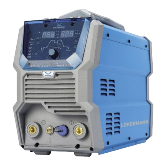
GRAND TIG 200
AC DC PULSE PFC MV
USER MANUAL
INVERTER Based Welding Machines
IMPORTANT: Read this OPERATOR MANUAL together
with PRESCRIPTION AND COMPLIANCE MANUAL before
to use this equipment. In case of loss one of two parts
contact immediately your dealer.
Allow the operator to consult this manual.
Advertisement
Table of Contents
Troubleshooting

Related Manuals for LOKERMANN Grand Tig 200


Summary of Contents for LOKERMANN Grand Tig 200
- Page 1 USER MANUAL INVERTER Based Welding Machines GRAND TIG 200 AC DC PULSE PFC MV IMPORTANT: Read this OPERATOR MANUAL together with PRESCRIPTION AND COMPLIANCE MANUAL before to use this equipment. In case of loss one of two parts contact immediately your dealer.
-
Page 2: Table Of Contents
CONTENT 1 INSTALLATION WARNING 2 OVERVIEW 2.1 Features 2.2 Technical Data 2.3 Brief Introduction 2.4 Duty cycle and Over-heat 2.5 Working Principle 2.6 Volt-Ampere Characteristic 3 INSTALLATION & OPERATION 3.1 Layout for the front and rear panel 3.2 Power supply input Connection 3.3 Installation &... -
Page 3: Installation Warning
This machine is certified according to 60974 -10:2014 Arc Welding Equipment Part 10: Electromagnetic compatibility (EMC) Installation requirement and the EUT belongs to Group 2 Class A. warning WARNING: This Class A equipment is intended for industrial use and it is not intended for use in residential locations where the elctric al power is provided by the public low... - Page 4 Welding cables The welding cables should be kept as short as possible and should be positioned close together, running at or close to the floor level. Equipotential bonding Bonding of all metallic objects in the surrounding area should be considered. However, metallic objects bonded to the work piece will increase the risk that the operator could receive an electric shock by touching these metallic objects and the electrode at the same time.
-
Page 5: Overview
Overview Features PFC Technology: Power factor more than 0.99. Multiple advantages such as energy saving and wider input voltage. Multivoltage: It can be supplied both with 110V and 230V. Lift TIG and HF Start Modes for versatility when welding around sensitive. -
Page 6: Technical Data
Net Weight(Kg) Brief Introduction Grand Tig 200 AC/DC Pulse PFC MV adopt the latest Pulse Width Modulation (PWM) technology and the Insulated Gate Bipolar Transistor (IGBT) power modules. It uses switching frequencies in the 20KHz-50KHz ranges so as to replace the traditional line-frequency transformer type welding machines. - Page 7 GRAND TIG 200 AC DC PULSE PFC MV Characteristics : MCU control system, responds immediately to any changes. High frequency and high voltage for arc igniting to ensure the success ratio of igniting arc, the reverse polarity ignition ensures good ignition behavior in TIG-AC welding.
-
Page 8: Duty Cycle And Over-Heat
When operating the machine again, the welding output current or the duty cycle should be reduced. Relation of welding current and duty cycle for GRAND TIG 200 AC DC PFC MV Working Principle The working principle of TIG series of welding machines is shown as the following figure. -
Page 9: Volt-Ampere Characteristic
Volt- Ampere Characteristic TIG series of welding machines has excellent volt-ampere characteristic. Referring to the following graph. In TIG welding, the relation between the rated loading voltage U2 and welding current I2 is as follows: When I2≤600A, U2=10+0.04 I2 ( V) ; When I2>600A, U2=34 ( V) . (V)... - Page 10 Control Panel (9) LH multifunction display* (10) RH multifunction display * (11) Power indicator (12) Water cooling system error indicator * (13) Alarm indicator * (14) Water /air cooling selection button * (15) Air cooling mode indicator (16) Water cooling mode indicator (17)...
- Page 11 Further Controls Explained LH Digital Multifunction Display (9) Before welding this displays the setting selected or being adjusted using the control knob (24). During welding it displays welding current. The parameter setting displayed is indicated by the LEDs beside the display; Current (A), Saved Setting (JOB), Time (S), Percentage (%) and Frequency (Hz).
- Page 12 Arc Force (21) An MMA welding power source is designed to produce constant output current (CC). This means with different types of electrode and arc length; the welding voltage varies to keep the current constant. This can cause instability in some welding conditions as MMA welding electrodes will have a minimum voltage they can operate with and still have a stable arc.
- Page 13 Pre gas flow setting indicator (1) Pre-flow controls the period shielding gas will flow for when the torch is triggered before the arc starts. This purges the work area of atmospheric gas which could contaminate the weld before the weld starts. Unit(S) and setting range (0.1-2S). Start current setting indicator (2) Available in 4T trigger mode, sets a welding current 10-100% of the main welding current activated when the trigger is held on to ‘latch’...
- Page 14 Pulse mode ‘off’ indicator (11) Pulse mode ‘On’ indicator (12) Clean Width Area/ AC Balance Adjustment (13) Only available in AC welding mode (27,28,29). Adjusts the balance as a percentage between the forward and reverse current cycles when welding in AC output mode. The reverse part of the AC cycle gives the ‘cleaning’...
- Page 15 TIG HF/ Lift Ignition Modes (31,32) For TIG welding process, contact of the torch tungsten to the workpiece will cause contamination of the tungsten and the workpiece that will adversely affect the weld quality, especially when the tungsten is electrically energised. HF Ignition (High Frequency) sends a pulse of high energy electricity through the torch system that is capable of ‘jumping’...
-
Page 16: Power Supply Input Connection
Water Cooling The welding machine is supplied standard with water cooled TIG torch. The correct coolant to use is a mixture of Mono Propylene Glycol and water in a 1:3 ratio (25% propylene glycol). Pure water may be used as a coolant liquid, though it is not recommended for the long term reliability of the water cooling system as it does not have the lubrication properties of glycol and does not provide protection against freezing. - Page 17 Connect the earth lead to “-”, tighten clockwise; Connect the earth clamp to the work piece. Contact with the work piece must be firm contact with clean, bare metal, with no corrosion, paint or scale at the contact point; Connect the electrode lead to “+”, tighten clockwise; Each machine is equipped with a power cable should be based on the input voltage welding power cable connected to the appropriate position, not to pick the wrong voltage;...
-
Page 18: Operation For Mma Welding
3.3.2 (1) According to the above method to install is correct, turn the power switch, so Operation that the power switch is “ON” position, then the power indicator light, the fan for MMA comes on, the device work properly. Welding (2) Set to ‘MMA’... -
Page 19: Operation For Tig Welding
Switch the ON/OFF Switch (located on the rear panel) to OFF. (1) Connect the earht lead to “+”, tighten clockwise. Connect the earth clamp to the work piece. Contact with the work piece must be firm contact with clean bare metal, with no corrosion, paint or scale at the contact point. (2) Connect the TIG torch cable to “-”, tighten clockwise. -
Page 20: Remote Current Control
Install the tungsten with approximately 3mm to 7mm sticking out from the gas cup, ensuring you have correct sized collet. Tighten the back cap. (8) Commence welding. If necessary, readjust the parameters control knob to obtain the welding condition re-quired. (9) After completion of welding the Power Source should be left turned ON for 2 to 3 minutes. -
Page 21: Tig Welding Techniques
3.4.4 Tig Welding Techniques TIG Welding Fusion Technique Manual TIG welding is often considered the most difficult of all the welding processes. Because the welder must maintain a short arc length, great care and skill are required to prevent contact between the electrode and the work piece. -
Page 22: Electrodes
3.4.5 Electrodes Tungsten Electrodes Tungsten Electrodes Rating for Welding Currents Tungsten DC Current Amps AC Current Amps AC Current Amps Diameter Torch Negative Un-Balanced Wave Balanced Wave 2% Thoriated 0.8% Zirconiated 0.8% Zirconiated 1.0mm 15-80 15-80 20-60 1.6mm 70-150 70-150 60-120 2.4mm 150-250... - Page 23 Electrode Tip/Flat The shape of the tungsten electrode tip is an important process variable in precision arc welding. A good selection of tip/flat size will balance the need for several advantages. The bigger the flat, the more likely arc wander will occur and the more difficult it will be to arc start.
-
Page 24: Tig Welding Trouble Shooting
3.4.6 TIG Welding trouble The following chart addresses some of the common problems of TIG welding. In all cases shooting of equipment malfunction, the manufacturer’s recommendations should be strictly adhered to and followed. Trouble Possible Reason Suggested Remedy Use pure Argon. Check cylinder Incorrect Gas or No Gas has gas, connected, turned on and torch valve is open... -
Page 25: Remote Control Configuration
Connect the torch to the DC- output Torch connected to DC + terminal Remove materials like paint, Contaminated base metal grease, oil, and dirt, including mill Unstable Arc scale from base metal. during welding Remove 10mm of contaminated Tungsten is contaminated tungsten and re grind the tungsten Lower torch so that the tungsten is Arc length too long... -
Page 26: Wire Foot Pedal Configuration
To synchronise a remote control to a machine, follow these instructions: Ensure the welding power supply is switched off. Press and hold the parameter select/adjust knob on the front panel of the power supply (2-4 seconds) while at the same time turning the machine ON using the ON-OFF switch on the back of the welding power supply. -
Page 27: Operation Environment
Remote Control Socket Socket Pin Function Be shorted with 2 Be shorted with 1 20k ohm (maximum) connection to 20k ohm remote control potentiometer Wiper arm connection to 20k ohm remote control potentiometer Zero ohm (minimum) connection to 20k ohm remote control potentiometer Not connected Not connected Trigger Switch Input... -
Page 28: Maintenance Troubleshooting
Maintenance & Troubleshooting In order to guarantee safe and proper operation of welding machines, they must be maintained regularly. Let customers understand the maintenance procedure of Maintenance welding machines. Enable customers to carry on simple examination and inspections. Do your best to reduce the fault rate and repair times of welding machines to lengthen service life of arc welding machine. -
Page 29: Troubleshooting
Troublesho- oting Before the welding machines are dispatche from the factory, they have already been tested and calibrated accurately. It is forbidden for anyone who is not authorized by our company to do any change to the equipment! Maintenance course must be operated carefully. If any wire becomes flexible or is misplaced, it maybe potential danger to user! Only professional maintenance staff that isauthorized by our company could overhaul the machine! -
Page 30: List Of Error Code
List of error code Error Type Error code Description Lamp status Red lamp(thermal Over-heating(1st thermal relay) protection) always on Red lamp(thermal Over-heating(2nd thermal relay) protection) always on Red lamp(thermal Thermal relay Over-heating(3rd thermal relay) protection) always on Red lamp(thermal Over-heating(4th thermal relay) protection) always on Red lamp(thermal Over-heating(Program in default) -
Page 31: Electrical Schematic Drawing
Electrical schematic drawing... - Page 32 LOKERMANN Srl, Via Produzione 16/18, 37044, Cologna Veneta, (VR) Italy, Tel: +39 0442 1722469 lokermann@lokermann.eu -www.lokermann.eu...
Need help?
Do you have a question about the Grand Tig 200 and is the answer not in the manual?
Questions and answers