Table of Contents
Advertisement
Quick Links
THANK YOU FOR USING OUR PRODUCTS
OPERATORS' MANUAL
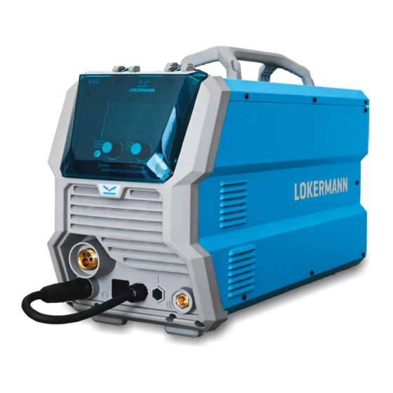
GRAND MIG 315 SYN COMPACT
INVERTER Based Welding Machines
IMPORTANT: Read this Owner's Manual Completely before attempting to use this
equipment. Save this manual and keep it handy for quick reference. Pay particular
attention to the safety instructions we have provided for your protection. Contact your
distributor if you do not fully understand this manual.
Advertisement
Table of Contents
Troubleshooting

Related Manuals for LOKERMANN GRAND MIG 315 SYN COMPACT


Summary of Contents for LOKERMANN GRAND MIG 315 SYN COMPACT
- Page 1 THANK YOU FOR USING OUR PRODUCTS OPERATORS’ MANUAL GRAND MIG 315 SYN COMPACT INVERTER Based Welding Machines IMPORTANT: Read this Owner’s Manual Completely before attempting to use this equipment. Save this manual and keep it handy for quick reference. Pay particular attention to the safety instructions we have provided for your protection.
-
Page 3: Table Of Contents
CONTENT CONTENT §1 Safety §2 Overview §2.1 Features §2.2 Technical Data §2.3 Duty cycle and Over-heat §2.4 Working Principle §2.5 Volt-Ampere Characteristic §3 Panel Functions & Descriptions §3.1 Machine Layout Description §3.2 Control Panel of welding machine §3.2.1 MIG Manual control panel §3.2.2 MIG SYN control panel §3.2.3 System setting panel §4 Installation &... -
Page 5: Safety
SAFETY §1 Safety Notice: The instructions are for reference only. The manufacturer reserves the right to explain the differences between the description and the product due to product changes and upgrades! - Page 6 SAFETY...
- Page 7 SAFETY...
- Page 8 SAFETY...
- Page 9 SAFETY...
- Page 10 SAFETY...
- Page 11 SAFETY...
- Page 12 SAFETY EMC device classification as per the rating plate or technical data.
-
Page 13: Overview
IP21S rating for environmental/safety protection. Internal wire feeder, gear driven for up to 300mm Ø spool. Tolerant to variable power supply. §2.2 Technical Data Models GRAND MIG 315 SYN COMPACT Parameters Input Voltage (V) 3~400±10% Frequency (HZ) -
Page 14: Duty Cycle And Over-Heat
OVERVIEW Circuit Breaker Standard LW31-32B-4AB-04/2 Protection class IP21S Dimensions (mm) 680*300*480 Weight (Kg) 27.5 Power Factor Note: The above parameters are subject to change with future machine improvement! §2.3 Duty cycle and Over-heat The letter “X” stands for Duty Cycle, which is defined as the portion of the time a welding machine can weld continuously with its rated output current within a certain time cycle (10 minutes). -
Page 15: Volt-Ampere Characteristic
OVERVIEW §2.5 Volt-Ampere Characteristic MIG series of welding machines has an excellent volt-ampere characteristic, whose graph is shown as the following figure. The relation between the rated loading voltage and welding current I is as follows: U =14+0.05I (V). (V) Volt-ampere characteristic The relation between the rated loading Working point... -
Page 16: Panel Functions & Descriptions
PANEL FUNCTIONS & DESCRIPTIONS §3 Panel Functions & Descriptions §3.1 Machine Layout Description 1. MIG torch euro connector. 2. Negative (-) welding power output connection socket. 3. MIG Torch Polarity Change Power Connection. 4. Positive (+) welding power output connection socket. 5. -
Page 17: Control Panel Of Welding Machine
PANEL FUNCTIONS & DESCRIPTIONS §3.2 Control Panel of welding machine §3.2.1 MIG Manual control panel 1. Welding mode button: Press it to select MIG Manual welding mode. 2. Manual shield gas check button. 3. L parameter knob: Rotate it to adjust wire feeding speed. In functional parameter interface, rotate it to select parameters. - Page 18 PANEL FUNCTIONS & DESCRIPTIONS 1. Trigger mode: 2T/ 4T. 2. Pre flow time: 0~2s. 3. Post flow time: 0~10s. 4. Burnback: 0~10. 5. Slow feed: 0~4. Trigger mode select: Burnback Short-circuit between welding wire and molten pool leads to the increase of current, which leads to the melting speed of welding wire too fast, and the wire feeding speed cannot keep up with, which makes the welding wire and workpiece disconnected.
-
Page 19: Mig Syn Control Panel
PANEL FUNCTIONS & DESCRIPTIONS §3.2.2 MIG SYN control panel The operator simply sets the welding current like MIG welding and the machine calculates the optimal voltage and wire speed for the material type, wire type and size and shielding gas being used. Obviously other variables such as welding joint type and thickness, air temperature affect the optimal voltage and wire feed setting, so the program provides a voltage fine tuning function for the synergic program selected. -
Page 20: Function Interface
PANEL FUNCTIONS & DESCRIPTIONS Function interface: 1. Trigger mode: 2T/ 4T/4T+ 2. Wire material: SS-metal solid-cored/Fe-metal solid-cored/ Fe-metal flux-cored/CuSi /SS-metal flux-cored. 3. Wire diameter: 0.8~1.6mm. 4. Shield gas: CO /Ar / 98%Ar+2%CO / 80%Ar+20%CO 5. Pre flow time: 0~2s. 6. Post flow time: 0~10s. 7. - Page 21 PANEL FUNCTIONS & DESCRIPTIONS...
-
Page 22: Installation & Operation
INSTALLATION & OPERATION §4 Installation & Operation §4.1 Installation & Operation for MIG Welding §4.1.1 Set up installation for MIG Welding (1) A- Insert the earth cable plug into the Negative (-) socket and twist to tighten. ( shielded wire) B- Insert the earth cable plug into the Positive (+) socket and twist to tighten. -
Page 23: Wire Feed Roller Selection
INSTALLATION & OPERATION (16) Set required parameters, such as welding voltage, welding current, wire feeding speed, burn back and 2T/4T. §4.1.2 Wire Feed Roller Selection The importance of smooth consistent wire feeding during MIG welding cannot be emphasized enough. Simply put the smoother the wire feed then the better the welding will be. -
Page 24: Wire Installation And Set Up Guide
INSTALLATION & OPERATION surface of the welding wire, and these small pieces will eventually go down into the liner. This will cause clogging in the liner and added friction that will lead to welding wire feed problems. A U groove wire can also be used for flux core wire without the wire particles coming of the wire surface. -
Page 25: Mig Torch Liner Types And Information
INSTALLATION & OPERATION §4.1.4 MIG Torch Liner Types and Information MIG Torch Liners The liner is both one of the simplest and most important components of a MIG gun. Its sole purpose is to guide the welding wire from the wire feeder, through the gun cable and up to the contact tip. -
Page 26: Mig Welding
INSTALLATION & OPERATION the end of the welding wire prior to feeding it down the liner. Sharp edges and burrs can score the inside of the liner and lead to blockages and accelerated wear. Polyamide Liners (PA) are made of carbon infused nylon and ideal for softer aluminum, copper alloy welding wires and push pull torch applications. - Page 27 INSTALLATION & OPERATION voltage. To follow are some basic guides to assist with your setup. Gun Position - Travel Direction, Work Angle: Gun position or technique usually refers to how the wire is directed at the base metal, the angle and travel direction chosen. Travel speed and work angle will determine the characteristic of the weld bead profile and degree of weld penetration.
- Page 28 INSTALLATION & OPERATION uneven penetration, poor gas shield and poor quality finished weld. Stick Out- Stick out is the length of the unmelted wire protruding from the end of the contact tip. A constant even stick out of 5-10mm will produce a stable arc, and an even current flow providing good penetration and even fusion.
- Page 29 INSTALLATION & OPERATION wire diameter and larger machine, check the recommended welding capability of your machine. As a guide refer to the “Welding Wire Thickness Chart” below. WELDING WIRE DIAMETER CHART MATERIALTHICKNESS RECOMMENDED WIRE DIAMETERS 0.8mm 0.9mm 1.0mm 1.2mm 1.6mm 2.0mm 2.5mm 3.0mm...
-
Page 30: Operation Environment
INSTALLATION & OPERATION §4.2 Operation environment Height above sea level ≤1000 M. Operation temperature range -10~+40°C. Air relative humidity is below 90% (20°C). Preferable site the machine some angles above the floor level, the maximum angle does not exceed 15℃. -
Page 31: Welding Trouble Shooting
WELDING TROUBLE SHOOTING §5 Welding trouble shooting §5.1 MIG welding trouble shooting The following chart addresses some of the common problems of MIG welding. In all cases of equipment malfunction, the manufacturer’s recommendations should be strictly adhered to and followed. Trouble Possible Reason Suggested Remedy... -
Page 32: Mig Wire Feed Trouble Shooting
WELDING TROUBLE SHOOTING Keep the arc at the leading edge of the weld pool. Gun angle to work should be between 5 & 15° Direct the arc at the weld joint Improper welding technique Adjust work angle or widen groove to proceeding weld access bottom during welding bead. - Page 33 WELDING TROUBLE SHOOTING Try to clear the liner by blowing out with Liner worn or clogged (the most compressed air as a temporary cure, it is common causes of bad feeding) recommended to replace the liner Wrong size liner Install the correct size liner Blocked or worn inlet guide tube Clear or replace the inlet guide tube Wire misaligned in drive roller...
-
Page 34: Maintenance & Troubleshooting
MAINTENANCE & TROUBLESHOOTING §6 Maintenance & Troubleshooting §6.1 Maintenance In order to guarantee safe and proper operation of welding machines, they must be maintained regularly. Let customers understand the maintenance procedure of welding machines. Enable customers to carry on simple examination and inspections. Do your best to reduce the fault rate and repair times of welding machines to lengthen service life of arc welding machine. -
Page 35: Troubleshooting
MAINTENANCE & TROUBLESHOOTING §6.2 Troubleshooting Before the welding machines are dispatched from the factory, they have already been tested and calibrated accurately. It is forbidden for anyone who is not authorized by our company to do any change to the equipment! ... -
Page 36: List Of Error Code
MAINTENANCE & TROUBLESHOOTING Troubles Reasons Solution Breaker damaged Change it Close the breaker, but the Fuse damaged Change it power light isn’t on Input power damaged Change it After welding machine is Fan damaged Change it over-heat, the fan doesn’t The cable is loose Screw the cable tight work... - Page 37 MAINTENANCE & TROUBLESHOOTING Yellow lamp (thermal Phase loss protection) always on Yellow lamp (lack water) No water always on No gas Red lamp always on Yellow lamp (thermal Welding machine Under voltage protection) always on Yellow lamp (thermal Over voltage protection) always on Yellow lamp (thermal Over current...
Need help?
Do you have a question about the GRAND MIG 315 SYN COMPACT and is the answer not in the manual?
Questions and answers