Advertisement
Quick Links
Advertisement

Related Manuals for LOKERMANN GRAND MIG 200 MULTI PFC SYN MV


Summary of Contents for LOKERMANN GRAND MIG 200 MULTI PFC SYN MV
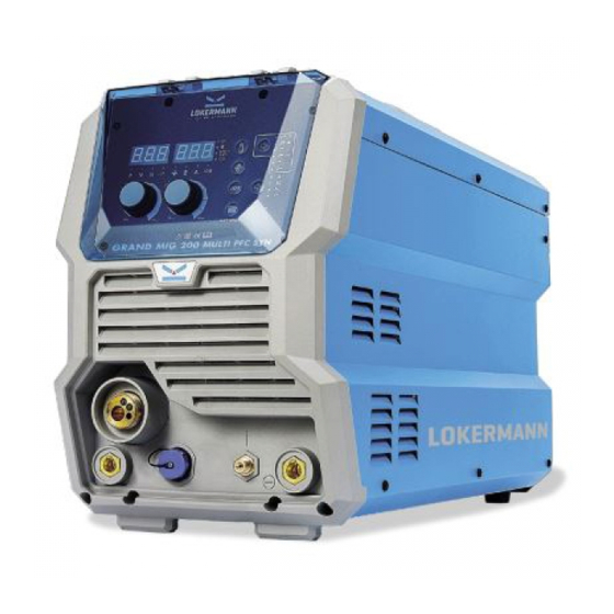
- Page 1 USER MANUAL INVERTER Based Welding Machines GRAND MIG 200 MULTI PFC SYN MV IMPORTANT: Read this OPERATOR MANUAL together with PRESCRIPTION AND COMPLIANCE MANUAL before to use this equipment. In case of loss one of two parts contact immediately your dealer. Allow the operator to consult this manual.
- Page 2 1 INSTALLATION WARNING 2 OVERVIEW 2.1 Brief Introduction 2.2 Working Principle 2.3 Volt-Ampere Characteristic 2.4 Principles of welding 3 INSTALLATION & ADJUSTMENT 3.1 Parameters 3.2 Duty cycle and Over-heat Equipment Connection 3.3.1 MIG Welding - gas shielded wire 3.3.2 MIG Welding - gasless wire 3.3.3 Spool Gun 3.3.4 MMA Welding 3.3.5 TIG Welding...
-
Page 3: Installation Warning
1. Installation warning This machine is certified according to 60974-10:2014 Arc Welding Equipment Part 10: Electromagnetic compatibility (EMC) requirement and the EUT belongs to Group 2 Class A. WARNING: This Class A equipment is intended for industrial use and it is not intended for use in residential locations where the elctrical power is provided by the public low-voltage supply system. - Page 4 Maintenance of the arc welding equipment The arc welding equipment should be routinely maintained according to this manual recommendations. All access and service doors and covers should be closed and properly fastened when the arc welding equipment is in operation. The arc welding equipment should not be modified in any way, except for those changes and adjustments covered in this manaul.
- Page 5 5. Rated Duty Cycle: GRAND MIG 200 MULTI PFC SYN MV = 200A @ 30%(40°C) GRAND MIG 200 MULTI PFC SYN MV has another feature: synergic control of the welding current and voltage. MIG series of welding machine is suitable for all positions welding for various plates made of...
- Page 6 2.2 Working Principle The working principle of MIG SERIES arc welding machine is shown as the following figure. Single-phase 110V/220V work frequency AC is rectified into DC, then is converted to medium frequency AC b y inverter device (IGBT), after reducing voltage by medium transformer (the main transformer) and rectifying by medium frequency rectifier (fast recovery diodes), and is outputted by inductance filtering.
-
Page 7: Installation And Adjustment
2.4 Principles of welding 3. Installation and Adjustment 3.1 Parameters Models GRAND MIG 200 MULTI PFC SYN MV Parameters Input Voltage(V) 1~110/120/130±10% 1~220/230/240±10% Frequency (HZ) 50/60 Input Current(A) MIG 38 MMA 32 TIG 29 MIG 29 MMA 30 TIG 20 Input Power(KW)... - Page 8 3.2 Duty cycle and Over- heat The letter “X” stands for Duty Cycle, which is defined as the portion of the time a welding machine can weld continuously with it’s rated output current within a certain time cycle (10 minutes). The relation between the duty cycle “X”...
- Page 9 3.3.2 MIG Welding - Gasless wire Switch the ON/OFF Switch (located on the rear panel) to OFF. (1) Insert the earth cable plug into the positive socket on the front of the machine and tighten it. (2) Plug the welding torch into the MIG torch connection socket on the front panel and tighten it. IMPORTANT : When connecting the torch be sure to tighten the connection.
- Page 10 (3) Connect the spool gun interface plug to the machine remote socket. Set the spool gun switch to 'on' position. (4) Connect the gas regulator to the Gas Cylinder and connect the gas line to the Gas Regulator. Check for Leaks! (5) Connect the gas line to gas connector on the rear panel.
- Page 11 Switch the ON/OFF Switch (located on the rear panel) to OFF. (1) Connect the earth lead to “-”, tighten clockwise; (2) Connect the earth clamp to the work piece. Contact with the work piece must be firm contact with clean, bare metal, with no corrosion, paint or scale at the contact point. (3) Connect the electrode lead to “+”, tighten clockwise;...
- Page 12 3.4 Maintenance of MIG Gun mechanism 3.4.1 Dissection graphics for the MIG GUN 3.4.2 Parts list for MIG GUN IFT0063 螺丝 M4X6 UNI 6107 IHJ0645 二氧化碳欧式后把套 ICG6000 导电嘴扳手 IHJ0028 电缆护套 12-16-25 MMQ IIC0500 带绝缘层送丝管0.6-0.8 3米 蓝色 ICN0663 同轴电缆组/16mmq/3米 IZT0071 送丝管锁紧螺母 Description QTY.
- Page 13 3. Changing the wire guide If the wire guide is too worn or totally clogged, change it to a new one acc o rding to the following instructions. Open the mounting nut of the wire guide which exposes the end of the wire guide. Straighten the welding gun’s cable and withdraw the wire guide from the gun.
-
Page 14: Operation
4. Operation 4.1 Layout for the front and rear panel 1. Power Led: Power led is lighted when open the machine. 2. Voltage LED: When the voltage LED is on, it display the actual output welding voltage. 3. Wire speed LED: You can use the parameter adjust/ select knob to set the wire speed when the wire speed LED is on. - Page 15 14. Output cathode 15. Power source input: To connect power source. 16. On/off switch : Control the power supply on and off. 17. Shield gas input joint: To connect one head of the gas hose while the other head of which is connected to argon gas cylinder.
- Page 16 5) Set the welding parameters as required using the parameter adjust/ select knob. You are now ready to weld! 4.2.2 SPOOL GUN mode operation 1) According to the above method to install is correct, turn the power switch to the “ON” position, the power L.E.D.
- Page 17 4.3 Welding parameters Process reference for CO2 butt welding of low carbon steel solid welding wire Material Root gap Wire Welding Welding Welding Gas- thickness G (MM) diameter current voltage speed flow (MM) (MM) (CM/MIN) rate (L/MIN) 60-70 16-16.5 50-60 75-85 17-17.5 50-60...
- Page 18 Nozzle and Material Wire Welding Welding Welding Gas-flow Welding workpiece thickness diameter current voltage speed rate position spacing (MM) (L/MIN) (MM) (CM/MIN) (MM) 80-100 19-21 40-50 12-15 10-15 90-100 19-21 40-50 13-16 13-15 Butt- 150-170 22-25 40-50 14-17 15-17 150-180 24-26 30-40 14-17...
-
Page 19: Maintenance And Troubleshooting
4.4 Operation environment ▲ Height above sea level ≤1000 M ▲ Operation temperature range -10~+40°C ▲ Air relative humidity is below 90 %( 20°C) ▲ Preferable site the machine some angles above the floor level, the maximum angle does not exceed 15℃. - Page 20 Date Maintenance items Observe that the knobs and switches in the front and at the back of arc welding machine are flexible and put correctly in place. If any knob has not been put correctly in place, please correct. If you can't correct or fix the knob, please replace immediately;...
- Page 21 Troubles Reasons Solution Breaker damaged Change it Close the breaker, but Fuse damaged Change it the power light isn’t on Input power damaged Change it After welding machine Fan damaged Change it is over-heat, the fan The cable is loose Screw the cable tight doesn’t work No gas in the gas cylinder...
- Page 22 5.3 List of error code Error Type Error code Description Lamp status Yellow lamp(thermal Over-heating(1st thermal relay) protection) always on Yellow lamp(thermal Over-heating(2nd thermal relay) protection) always on Yellow lamp(thermal Thermal relay Over-heating(3rd thermal relay) protection) always on Yellow lamp(thermal Over-heating(4th thermal relay) protection) always on Yellow lamp(thermal...
- Page 23 5.4 Electrical schematic drawing...
- Page 24 LOKERMANN Srl, Via Produzione 16/18, 37044, Cologna Veneta, (VR)-Italy, Tel: +39 0442 1722469 lokermann@lokermann.eu - www.lokermann.eu...
Need help?
Do you have a question about the GRAND MIG 200 MULTI PFC SYN MV and is the answer not in the manual?
Questions and answers