Table of Contents
Advertisement
Quick Links
THANK YOU FOR USING OUR PRODUCTS
OPERATOR'S MANUAL
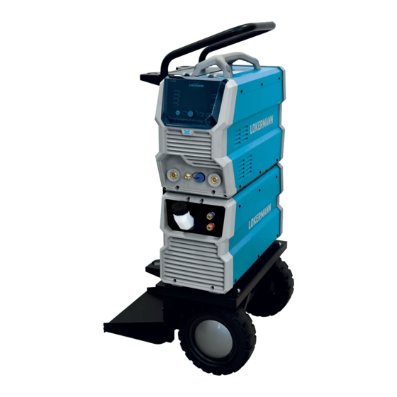
GRAND TIG 202 AC DC PULSE PFC
INVERTER AC DC PULSE TIG WELDER
IMPORTANT: Read this Owner's Manual Completely before attempting to use this
equipment. Save this manual and keep it handy for quick reference. Pay particular
attention to the safety instructions we have provided for your protection. Contact your
distributor if you do not fully understand this manual.
Advertisement
Table of Contents
Troubleshooting

Related Manuals for LOKERMANN GRAND TIG 202 AC DC PULSE PFC


Summary of Contents for LOKERMANN GRAND TIG 202 AC DC PULSE PFC
- Page 1 THANK YOU FOR USING OUR PRODUCTS OPERATOR’S MANUAL GRAND TIG 202 AC DC PULSE PFC INVERTER AC DC PULSE TIG WELDER IMPORTANT: Read this Owner’s Manual Completely before attempting to use this equipment. Save this manual and keep it handy for quick reference. Pay particular attention to the safety instructions we have provided for your protection.
-
Page 2: Table Of Contents
SAFETY CONTENT §1 SAFETY..............................1 §2 SUMMARY..............................9 §2.1 Features..............................9 §2.2 Brief Introduction..........................10 §2.3 Parameters............................. 12 §2.4 Duty cycle & Over heat........................13 §2.5 Working Principle..........................13 §2.6 Volt-Ampere Characteristic....................... 14 §3 Installation & Operation......................... 15 §3.1 Layout for Front and Rear panel.....................15 §3.1.1 Layout for welder............................15 §3.1.2 Layout for water cooling..........................16 §3.2 Layout for Control panel........................ - Page 3 SAFETY §3.6 Operation Notices..........................40 §4 Maintenance & Troubleshooting....................41 §4.1 Maintenance............................41 §4.2 Troubleshooting........................... 42 §4.3 MMA Welding - Trouble Shooting....................43 §4.4 DC TIG Welding - Trouble Shooting....................45 §4.5 List of error code..........................47...
- Page 4 SAFETY...
-
Page 5: Safety
SAFETY §1 SAFETY Notice: The instructions are for reference only. The manufacturer reserves the right to explain the differences between the description and the product due to product changes and upgrades! The device is manufactured using state-of-the-art technology and according to recognised safety standards. If used incorrectly or misused, however, it can cause: ... - Page 6 SAFETY cause damage, please avoid the above situation. Excessive ambient temperature will cause the machine heat dissipation is not smooth, so that the internal components of the machine heat seriously. Usually the maximum operating temperature is 104°F (40°C). Low temperature may lead to performance degradation or damage of components inside the product, resulting in ice inside the water tank.
- Page 7 SAFETY Shafts Wire spools and welding wire Many harmful phenomena, such as noise, bright light and harmful gas, will inevitably occur in the welding process. In order to avoid harmful By product phenomena causing harm to the human body, it is necessary to make corresponding preparations in advance.
- Page 8 SAFETY Welding may produce fumes and gases hazardous to health. Avoid breathing these fumes and gases. Do not breathe the smoke and gas generated whilst welding or cutting, keep your head out of the fumes. Use enough ventilation and/or exhaust at the arc to keep fumes and gases away from the breathing zone.
- Page 9 SAFETY Flying sparks from the welding arc, hot work piece, and hot equipment can cause fires and burns. Accidental contact of electrode to metal objects can cause sparks, explosion, overheating or fire. Welding sparks and hot materials from welding can easily go through small cracks and openings to adjacent areas.
- Page 10 SAFETY Use only compressed gas cylinders containing the correct shielding gas for the process used and properly operating regulators designed for the gas and pressure used. All hoses, fittings, etc. should be suitable for the application and maintained in good condition. ...
-
Page 11: Safety Device
SAFETY Don’t sling cables or leads around either the body or parts of the body. The electrode (rod electrode, tungsten electrode, welding wire, etc) must Never be immersed. Never be touched when current is flowing. When the machine is connected to the power supply, there is electricity inside the machine. - Page 12 SAFETY Radiation Class A Device. Only can be used in the industrial area. If it is used in other area, it may cause connection and radiation problems of circuit. Radiation Class B device. Satisfy the emissions criteria for residential and industrial areas. This is also true for residential areas in which the energy is supplied from the public low-voltage mains.
-
Page 13: Summary
SUMMARY §2 SUMMARY §2.1 Features New appearance and new panel design: More trendy and humanized. LCD screen for accurate setting & feedback of welding output. PFC Technology: Power factor more than 0.99. Multiple advantages such as energy saving welder input... -
Page 14: Brief Introduction
SUMMARY §2.2 Brief Introduction TIG-series welding machine adopts the latest pulse width modulation (PWM) technology and insulated gate bipolar transistor (IGBT) power module, which can change work frequency to medium frequency so as to replace the traditional hulking work frequency transformer with the cabinet medium frequency transformer. Thus, it is characterized with portable, small size, light weight, low consumption and etc. - Page 15 SUMMARY 5. DC Pulsed TIG has the following characters: 1) Pulse heating. Metal in Molten pool has short time on high temperature status and freezes quickly, which can reduce the possibility to produce hot crack of the materials with thermal sensitivity. 2) The workpiece gets little heat.
-
Page 16: Parameters
SUMMARY §2.3 Parameters Models GRAND TIG 202 AC DC PULSE PFC Parameters Power source 1-110V±10% 1-230V±10% Frequency (Hz) 50/60 Rated input current (A) 30.7 33.2 35.8 38.3 19.3 20.5 28.0 29.7 Rated input power (kVA) 3.37 3.64 3.92 4.20 4.45 4.70... -
Page 17: Duty Cycle & Over Heat
The letter “X” stands for Duty Cycle, Relation of welding current and duty cycle which is defined as the portion of the GRAND TIG 202 AC DC PULSE PFC time a welding machine can weld continuously with its rated output current within a certain time cycle (10 minutes). -
Page 18: Volt-Ampere Characteristic
SUMMARY §2.6 Volt-Ampere Characteristic TIG-series welding machine has an excellent volt-ampere characteristic, whose graph is shown as the following figure. The relation between the conventional rated loading voltage U and the conventional welding current I is as follows: When I ≤600A, U =10+0.04I (V);... -
Page 19: Installation & Operation
INSTALLATION & OPERATION §3 Installation & Operation §3.1 Layout for Front and Rear panel §3.1.1 Layout for welder TIG torch remote connection socket. “-” Output terminal. “+” Output terminal. TIG torch gas connector. Input power cable. Power switch. Water cooler remote connection socket. Inlet gas connector. -
Page 20: Layout For Water Cooling
INSTALLATION & OPERATION §3.1.2 Layout for water cooling Intake: From here, water or coolant, antifreeze, etc. can be injected into tank. Water outlet for TIG (red).* Backwater inlet for TIG (blue).* The water cooling control connector.* The words marked * are explained in detail below. Inlet (2) and outlet (3) for TIG The two nozzles on the both side of the intake (1) are used for TIG operation and can be connected to the nozzles on TIG welding torch. -
Page 21: Layout For Control Panel
INSTALLATION & OPERATION time. §3.2 Layout for Control panel §3.2.1 Control panel 1. Welding mode button: Press it to select MMA/ HF TIG/ LIFT TIG welding mode. 2. Output waveform button.* 3. Trigger mode selecting button: Press it to select 2T or 4T trigger mode. * 4. - Page 22 INSTALLATION & OPERATION 10. Parameter A button: Press it to select Hot start or Fre. /Balance. If the button is not pressed within 3s, the selection will be automatically removed. 11. Screen: It will show all welding parameters, such as welding voltage, welding current and other parameters set.
- Page 23 INSTALLATION & OPERATION Introduction: (1) 0: Press the gun switch and hold it. Electromagnetic gas valve is turned on. The shielding gas stars to flow. (2) 0~t1: Pre-gas time (0.1~2.0s) (3) t1~t2: Arc is ignited and the output current rises to the setting welding current (I ) from the min welding current.
- Page 24 INSTALLATION & OPERATION is useful to longer welds as the trigger is not required to be held on continuously. TIG series of welding machines also has more current control options that can be used in 4T mode. The start current and crater current can be pre-set. This function can compensate the possible crater that appears at the beginning and end of the welding.
- Page 25 INSTALLATION & OPERATION panel (0.0~10S); (12) t7: Electromagnetic valve is closed and stop argon flowing. Welding is finished. Function A button (6) In HF TIG/ Lift TIG, press it to select Pre-gas time, Pre current and Up slope time; In Spot welding mode, press it to select Pre-gas time;...
-
Page 26: Mma Display Introduction
INSTALLATION & OPERATION §3.2.2 MMA display introduction 1. Welding mode button: Press it to enter MMA welding mode. 2. Out waveform button: Press it to select DC output or AC Square wave output. 3. Parameter A button: Press it to select Hot start. Setting range: 0~10. 4. -
Page 27: Hf/Lift Tig Display Introduction
INSTALLATION & OPERATION §3.2.3 HF/LIFT TIG display introduction 1. Welding mode button: Press it to enter HF TIG or Lift TIG welding mode. 2. Output waveform button: Press it to select DC output or AC wave output. 3. Trigger mode button: Press it to select 2T or 4T trigger mode. 4. -
Page 28: Tig Pulse Display Introduction
INSTALLATION & OPERATION show parameter selected. 11. Cooling mode display. 12. Parameter A button: Press it to select AC Balance (-5 to +5) or AC Frequency (50~250Hz). 13. Parameter B button: Press it to select diameter size. §3.2.4 TIG Pulse display introduction 1. -
Page 29: Job Program Introduction
INSTALLATION & OPERATION 2. T display: 0.2~1.0s. 3. T display: off~10.0s. §3.2.6 JOB Program introduction 1. Welding mode display: Here are selected welding states. 2. Parameters display: Here are all selected parameters values. 3. JOB number: A total 1~10 JOB numbers can store or call the selected parameters by JOB button. -
Page 30: Installation & Operation For Mma Welding
INSTALLATION & OPERATION §3.3 Installation & Operation for MMA welding §3.3.1 Set up installation for MMA Welding Connection of Output Cables Two sockets are available on this welding machine. For MMA welding the electrode holder is shown be connected to the positive socket, while the earth lead (work piece) is connected to the negative socket, this is known as DCEP. -
Page 31: Operation For Mma Welding
INSTALLATION & OPERATION (2) Connect the earth clamp to the work piece. Contact with the work piece must be firm contact with clean, bare metal, with no corrosion, paint or scale at the contact point. (3) Connect the electrode lead to “+”, tighten clockwise; (4) Each machine is equipped with a power cable should be based on the input voltage welding power cable connected to the appropriate position, not to pick the wrong voltage;... -
Page 32: Mma Welding
INSTALLATION & OPERATION you choose incorrectly will result in arc instability and spatter large adhesion and other phenomena, such cases can be quickly reversed to joints. If the work piece distance from the welding machine, the second line (electrode holder and ground) is longer, so choose the appropriate conductor cross-sectional area should be larger to reduce cable voltage drop. -
Page 33: Mma Welding Fundamentals
INSTALLATION & OPERATION atmosphere of protective gas. Manual metal arc (stick) electrodes have a solid metal wire core and a flux coating. These electrodes are identified by the wire diameter and by a series of letters and numbers. The letters and numbers identify the metal alloy and the intended use of the electrode. -
Page 34: Arc Length
INSTALLATION & OPERATION The size of the electrode generally depends on the thickness of the section being welded, and the thicker the section the larger the electrode required. The table gives the maximum size of electrodes that may be used for various thicknesses of section base on using a general purpose type 6013 electrode. -
Page 35: Travel Speed
INSTALLATION & OPERATION travel. When vertical up welding, the angle of the electrode should be between 80 and 90 degrees to the work piece. Travel Speed The electrode should be moved along in the direction of the joint being welded at a speed that will give the size of run required. - Page 36 INSTALLATION & OPERATION (1) Insert the earth cable plug into the positive socket on the front of the machine and tighten it. (2) Plug the welding torch into the negative socket on the front panel, and tighten it. (3) Connect the gas line of TIG Gun to outlet gas connector on the front of the machine. (4) Connect the control cable of torch switch to 12 pin socket on the front of the machine.
-
Page 37: Dc Tig Welding
INSTALLATION & OPERATION the air cooling mode. (9) Connect the power cable of welding machine with the output switch in electric box on site. Turn on the power switch. (10) Carefully open the valve of the gas cylinder, set the required gas flow rate. (11) Select “Lift TIG”... -
Page 38: Tig Welding Fusion Technique
INSTALLATION & OPERATION DC TIG welding is a process in which an arc is struck between a TUNGSTEN electrode and the metal work piece. The weld area is shielded by an inert gas flow to prevent contamination of the tungsten, molten pool and weld area. When the TIG arc is struck the inert gas is ionized and superheated changing its molecular structure which converts it into a plasma stream. - Page 39 INSTALLATION & OPERATION butt joints. This is known as Fusion welding where the edges of the metal pieces are melted together using only the heat and arc force generated by the TIG arc. Once the arc is started the torch tungsten is held in place until a weld pool is created, a circular movement of the tungsten will assist is creating a weld pool of the desired size.
-
Page 40: Tungsten Electrodes
INSTALLATION & OPERATION §3.4.4 Tungsten Electrodes Tungsten is a rare metallic element used for manufacturing TIG welding electrodes. The TIG process relies on tungsten’s hardness and high-temperature resistance to carry the welding current to the arc. Tungsten has the highest melting point of any metal, 3,410 degrees Celsius. - Page 41 INSTALLATION & OPERATION in the grinding of the tungsten. Follow the manufacturer’s warnings, instructions, and the Material Safety Data Sheet (MSDS) for its use. E3 (Color Code: Purple) E3 tungsten electrodes (AWS classification EWG) contain a minimum of 98% percent tungsten and up to 1.5 percent Lanthanum and small percentages of Zirconium and Yttrium they are called E3 Tungsten.
-
Page 42: Tungsten Preparation
INSTALLATION & OPERATION Lanthanated tungsten electrodes (AWS classification EWLa-1.5) contain a minimum of 97.80 percent tungsten and 1.30 percent to 1.70 percent lanthanum, and are known as 1.5 percent lanthanated. These electrodes have excellent arc starting, a low burn off rate, good arc stability, and excellent re-ignition characteristics. - Page 43 INSTALLATION & OPERATION hard material, the surface of a diamond wheel is harder, and this makes for smooth grinding. Grinding without diamond wheels, such as Aluminum oxide wheels, can lead to jagged edges, imperfections, or poor surface finishes not visible to the eye that will contribute to weld inconsistency and weld defects.
-
Page 44: Operation Environment
INSTALLATION & OPERATION Electrode Included Angle/Taper - DC Welding Tungsten electrodes for DC welding should be ground longitudinally and concentrically with diamond wheels to a specific included angle in conjunction with the tip/flat preparation. Different angles produce different arc shapes and offer different weld penetration capabilities. -
Page 45: Operation Notices
INSTALLATION & OPERATION does not exceed 15°. Protect the machine against heavy rain or in hot circumstance against direct sunshine. The content of dust, acid, corrosive gas in the surrounding air or substance cannot exceed normal standard. Take care that there is sufficient ventilation during welding. There is at least 30cm free distance between the machine and wall. -
Page 46: Maintenance & Troubleshooting
MAINTENANCE & TROUBLESHOOTING §4 Maintenance & Troubleshooting §4.1 Maintenance In order to guarantee that arc welding machine works high-efficiently and in safety, it must be maintained regularly. Let customers understand the maintenance methods and means of arc welding machine more, enable customers to carry on simple examination and safeguarding by oneself, try one's best to reduce the fault rate and repair times of welding machine,... -
Page 47: Troubleshooting
MAINTENANCE & TROUBLESHOOTING Observe that whether the fast connector is loose or overheated. If the arc welding machine has the above problems, it should be fastened or changed. Observe that whether the current output cable is damaged. If it is damaged, it should be wrapped up, insulated or changed. - Page 48 MAINTENANCE & TROUBLESHOOTING Troubles Reasons Solution displayed doesn’t the control board. accord with the set Adjust potentiometer in the The min value is not accordant value. current meter. no-load voltage The machine is damaged Check the main circuit output (MMA) The welding cable is not connected Connect the welding cable to with the two output of the welder.
-
Page 49: Mma Welding - Trouble Shooting
MAINTENANCE & TROUBLESHOOTING §4.3 MMA Welding - Trouble Shooting The following chart addresses some of the common problems of MMA welding. In all cases of equipment malfunction, the manufacturer’s recommendations should be strictly adhered to and followed. Trouble Possible Reason Suggested Remedy Check earth lead is connected. -
Page 50: Dc Tig Welding - Trouble Shooting
MAINTENANCE & TROUBLESHOOTING seek assistance for the correct technique Check the joint design and fit up, welding Poor joint preparation and or make sure the material is not too joint design thick. Seek assistance for the correct joint design and fit up Electrode welds Change the polarity, check the with different or... - Page 51 MAINTENANCE & TROUBLESHOOTING 20~40 CFH (6~12 l/min). Check hoses and fittings for leaks Remove moisture and materials like Contaminated base metal paint, grease, oil and dirt from base metal Remove all grease, oil or moisture Contaminated filler wire from filler metal Check the filler wire and change if Incorrect filler wire necessary...
-
Page 52: List Of Error Code
MAINTENANCE & TROUBLESHOOTING tungsten if required Loose connection Check all connectors and tighten Earth clamp not connected to Connect the earth clamp directly to work the work piece wherever possible §4.5 List of error code Error Type Error code Description Over-heating (1st thermal relay) Over-heating (2nd thermal relay) Thermal relay...
Need help?
Do you have a question about the GRAND TIG 202 AC DC PULSE PFC and is the answer not in the manual?
Questions and answers