Table of Contents
Advertisement
Quick Links
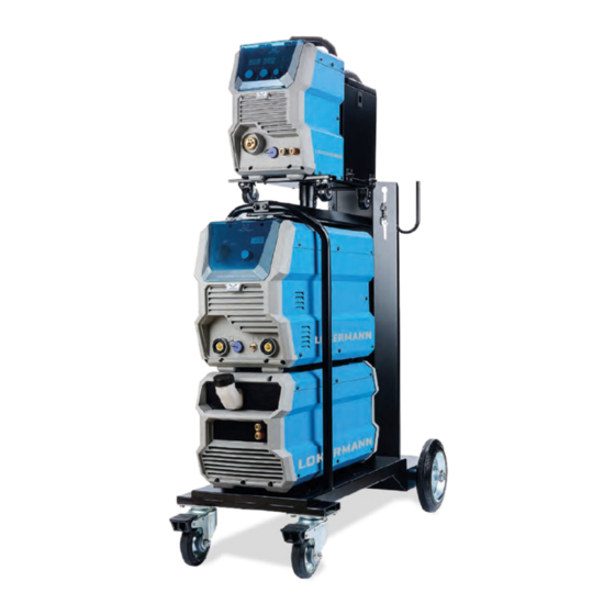
GRAND MIG 351
M U L T I
GRAND MIG 501
M U L T I
USER MANUAL
INVERTER Based Welding Machines
S Y N
S Y N
IMPORTANT: Read this OPERATOR MANUAL together
with PRESCRIPTION AND COMPLIANCE MANUAL before
to use this equipment. In case of loss one of two parts
contact immediately your dealer.
Allow the operator to consult this manual.
Advertisement
Table of Contents
Troubleshooting


Need help?
Do you have a question about the GRAND MIG 351 MULTI SYN and is the answer not in the manual?
Questions and answers