Table of Contents
Advertisement
Quick Links
Advertisement
Table of Contents

Related Manuals for LOKERMANN GRAND MIG 315 COMPACT


Summary of Contents for LOKERMANN GRAND MIG 315 COMPACT
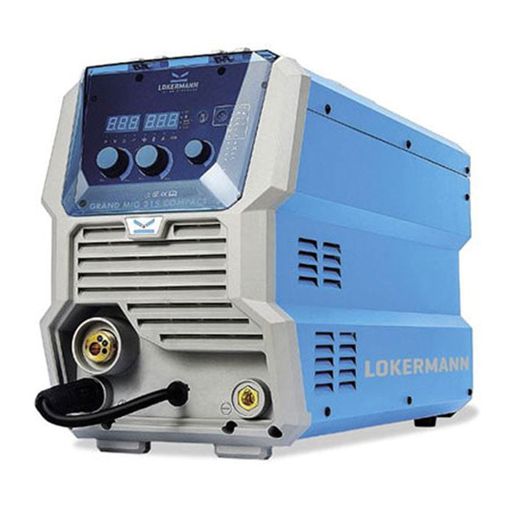
- Page 1 USER MANUAL INVERTER Based Welding Machines GRAND MIG 315 COMPACT IMPORTANT: Read this OPERATOR MANUAL together with PRESCRIPTION AND COMPLIANCE MANUAL before to use this equipment. In case of loss one of two parts contact immediately your dealer. Allow the operator to consult this manual.
-
Page 2: Table Of Contents
CONTENT 1 INSTALLATION WARNING 2 OVERVIEW 2.1 Brief Introduction 2.2 Working Principle 2.3 Volt-Ampere Characteristic 2.4 Principles of welding 3 INSTALLATION AND ADJUSTMENT 3.1 Parameters 3.2 Duty cycle and Over-heat 3.3 Equipment Connection 3.4 Operation for MIG GUN 4 OPERATION 4.1 Layout for the front and rear panel 4.2 Wire Feeder of welding machine 4.3 Welding operation... -
Page 3: Installation Warning
INSTALLATION WARNING This machine is certified according to 60974-10:2014 Arc Welding Equipment Part 10: Electromagnetic Installation compatibility (EMC) requirement and the EUT belongs to Group 2 Class A. warning WARNING: This Class A equipment is intended for industrial use and it is not intended for use in residential locations where the elctrical power is provided by the public low-voltage supply system. -
Page 4: Overview
Overview GRAND MIG 315 COMPACT adopts the latest Pulse Width Modulation (PWM) technology and the Brief Insulated Gate Bipolar Transistor (IGBT) power modules. It uses switching frequencies in the 20KHz-50KHz range so as to replace the traditional line-frequency transformer type welding machines. -
Page 5: Volt-Ampere Characteristic
(V) Volt-ampere characteristic The relation between the rated loading Working point voltage and welding current (A) Principles of welding Installation Models GRAND MIG 315 COMPACT Parameters Adjustment Input Voltage(V) 3~380/400/440±10% Frequency (HZ) 50/60 Input Current (I1max) (A) Input Power(KW) Parameters Welding Current(A)... -
Page 6: Duty Cycle And Over-Heat
Duty cycle The letter “X” stands for Duty Cycle, which is defined as the portion of the time a welding machine can weld continuously with it’s rated output current within a certain time cycle (10 minutes). Over-heat The relation between the duty cycle “X” and the output welding current “I” is shown as the right figure. -
Page 7: Operation For Mig Gun
Operation for MIG 1. Service the wire feed mechanism at least every time the reel is changed. · Check the wear of the feed roll groove and change the feed roll when necessary. · Clean the welding gun wire guide with compressed air. 2. -
Page 8: Layout For The Front And Rear Panel
Operation Layout for the front and rear panel Manual inch wire switch & test gas switch: left for manual inch wire and right for test gas. Choose welding mode switch: left for 2T welding mode and right for 4T welding mode. Burn back knob Wave control knob: Controls arc characteristics, Determines the rate at which the amperage rises when a short circuit is produced. -
Page 9: Welding Operation
Welding (1) Place the Wire Spool onto the Spool Holder. Snip the wire from the spool being sure to hold the operation wire to prevent rapid uncoiling. Feed the wire into the wire feeder inlet guide tube through to the drive roller. -
Page 10: Wire Feed Roller Selection
4.3.1 Wire Feed The importance of smooth consistent wire feeding during MIG welding cannot be emphasized enough. Roller Simply put the smoother the wire feed then the better the welding will be. Selection Feed rollers or drive rollers are used to feed the wire mechanically along the length of the welding gun. Feed rollers are designed to be used for certain types of welding wire and they have different types of grooves machined in them to accommodate the different types of wire. -
Page 11: Wire Installation And Set Up Guide
4.3.2 Again the importance of smooth consistent wire feeding during MIG welding cannot be emphasized enough. The correct installation of the wire spool and the wire into the wire feed unit is critical to Wire achieving an even and consistent wire feed. A high percentage of faults with mig welders emanate Installation from poor set up of the wire into the wire feeder. -
Page 12: Mig Torch Liner Types And Information
4.3.4 MIG Torch Liner Types MIG Torch Liners The liner is both one of the simplest and most important components of a MIG gun. Its sole purpose is to guide the welding wire from the wire feeder, through the gun cable and up to the contact tip. Information Steel Liners Most MIG gun liners are made from coiled steel wire also known as piano wire, which provides the... - Page 13 Good weld quality and weld profile depends on gun angle, direction of travel, electrode extension (stick out), travel speed, thickness of base metal, wire feed speed and arc voltage. To follow are some basic guides to assist with your setup. Gun Position - Travel Direction, Work Angle: gun position or technique usually refers to how the wire is directed at the base metal, the angle and travel direction chosen.
- Page 14 Angle to Work - The work angle is the forward back angle of the gun relative to the work piece. The correct work angle provides good bead shape, prevents undercut, uneven penetration, poor gas shield and poor quality finished weld. Stick Out- Stick out is the length of the unmelted wire protruding from the end of the contact tip.
- Page 15 Too Fast Travel Speed - A too fast travel speed produces too little heat per mm of travel resulting in less penetration and reduced weld fusion, the weld bead solidifies very quickly trapping gases inside the weld metal causing porosity. Undercutting of the base metal can also occur and an unfilled groove in the base metal is created when the travel speed is too fast to allow molten metal to flow into the weld crater created by the arc heat.
-
Page 16: Welding Parameters
Process reference for CO2 butt welding of low carbon steel solid welding wire Material Root gap Wire Welding Welding Welding Gas- thickness G (MM) diameter current voltage speed flow (MM) (MM) (CM/MIN) rate (L/MIN) 4.3.6 60-70 16-16.5 50-60 75-85 17-17.5 50-60 10-15 Welding... -
Page 17: Operation Environment
Operation environment ▲ Height above sea level ≤1000 M ▲ Operation temperature range -10〜+40°C ▲ Air relative humidity is below 90 %( 20°C) ▲ Preferable site the machine some angles above the floor level, the maximum angle does not exceed 15℃. ▲... -
Page 18: Troubleshooting
Date Maintenance items Observe that the knobs and switches in the front and at the back of arc welding machine are flexible and put correctly in place. If any knob has not been put correctly in place, please correct. If you can't correct or fix the knob, please replace immediately;... -
Page 19: List Of Error Code
Error Type Error code Description Lamp status List of Yellow lamp(thermal Over-heating(1st thermal relay) protection) always on error code Yellow lamp(thermal Over-heating(2nd thermal relay) protection) always on Yellow lamp(thermal Thermal relay Over-heating(3rd thermal relay) protection) always on Yellow lamp(thermal Over-heating(4th thermal relay) protection) always on Yellow lamp(thermal Over-heating(Program in default) - Page 20 LOKERMANN Srl, Via Produzione 16/18, 37044, Cologna Veneta, (VR) Italy, Tel: +39 0442 1722469 lokermann@lokermann.eu -www.lokermann.eu...
Need help?
Do you have a question about the GRAND MIG 315 COMPACT and is the answer not in the manual?
Questions and answers