Table of Contents
Advertisement
Quick Links
Advertisement
Table of Contents

Related Manuals for LEMKEN Kristall 9 K


Summary of Contents for LEMKEN Kristall 9 K
- Page 1 Operating Instructions Cultivator Kristall 9 K / KU - EN - Item no. 175_4840 2/04.11 LEMKEN GmbH & Co. KG Weseler Straße 5, D-46519 Alpen / PO Box 11 60, D-46515 Alpen Telephone (0 28 02) 81-0, Fax (0 28 02) 81-220...
- Page 3 However, this brief instruction is not a substitute for thorough study of the operating instructions. These operating instructions will help to familiarise you with the LEMKEN GmbH & Co. KG device and the options available for using it.
- Page 4 Remember that you should only use genuine LEMKEN spare parts. Reproduction parts have a negative influence on the function of the device, have a shorter ser- vice life and present risks and hazards that cannot be estimated by LEMKEN GmbH & Co. KG. They also increase the maintenance costs.
-
Page 5: Table Of Contents
Contents CONTENTS Contents ........................... 3 General information ....................8 Liability........................... 8 Guarantee........................8 Copyright ........................9 Optional accessories ....................9 Symbols used in the Operating Instructions............10 Hazard classes ......................10 Information........................11 Environmental protection ................... 11 Indication of passages....................11 Safety measures and precautions................. - Page 6 Contents Operation on public highways ................... 23 3.9.1 Lighting system and identification ................23 3.9.2 Requirements of the tractor..................23 3.9.3 Axle loads......................... 24 3.9.4 Check before departure ................... 28 3.9.5 Correct behaviour in road traffic ................28 3.10 Obligation of the operator ..................29 3.11 Operating the device safely..................
- Page 7 Contents Three-point linkage ..................... 39 Hydraulic system......................41 6.7.1 Transport........................41 6.7.2 Work assignment ..................... 41 6.7.3 Coupling and uncoupling..................41 Coupling and uncoupling implement..............42 Coupling........................44 Dismounting ........................ 46 Drawbar ........................47 Upper control link......................48 Safety equipment ....................49 General information ....................
- Page 8 Contents 10.7.3 Edge discs ......................68 10.8 Rollers .......................... 69 10.8.1 General information ....................69 10.8.2 Blade rollers......................70 10.8.3 Pressure load on rollers - Intake behaviour ............72 10.9 Turning at the headland....................77 11 Switching over to different share systems............78 11.1 Share tips, guide plates and wing shares ..............
- Page 9 Contents 13.4 Maintenance intervals ....................90 13.4.1 After the initial start-up (at the latest after 2 hours)..........90 13.4.2 Daily inspection ....................90 13.4.3 Weekly inspection....................91 13.5 Tightening torques...................... 92 13.5.1 Wheel nuts......................92 13.5.2 Other screw connections ..................92 13.6 Checking connections to the tractor .................
-
Page 10: General Information
Co. KG, in particular Section IX, shall apply. Liability. In line with the dimensions cited in these conditions the LEMKEN GmbH & Co. KG shall not be held liable for any personal or material damage, when such damage is caused by one or more of the following reasons: ... -
Page 11: Copyright
Infringements will result in a claim for damages. Optional accessories LEMKEN implements may be equipped with various accessories. The operating instructions below describe both series components and optional accessories. Please note: These accessories will vary depending on the type of equipment. -
Page 12: Symbols Used In The Operating Instructions
Symbols used in the Operating Instructions SYMBOLS USED IN THE OPERATING INSTRUCTIONS Hazard classes The following symbols are used in the Operating Instructions for particularly im- portant information: DANGER Denotes an imminent hazard with high risk, which will result in death or severe physical injury, if not avoided. -
Page 13: Information
Symbols used in the Operating Instructions Information Denotes special user tips and other particularly useful or important information for operation and efficient utilisation. Environmental protection Indication of special recycling and environmental protection measures. Indication of passages The following symbols are used for particular passages in the operating instruc- tions: ... -
Page 14: Safety Measures And Precautions
Safety measures and precautions SAFETY MEASURES AND PRECAUTIONS General safety instructions for the operator are specified in the chapter entitled "Safety measures and precautions". At the start of some main chapters the safety instructions, which refer to all work to be carried out in this chapter, are listed to- gether. -
Page 15: Safety Equipment On The Device
Safety measures and precautions Safety equipment on the device To protect the user and the device, the device features special safety equipment. Always keep all safety equipment in working order. Warning signs with light Hydraulic fold-out lock Guide rod for rollers Protective tarpaulin... -
Page 16: Safety And Warning Signs
Safety measures and precautions Safety and warning signs 3.4.1 General information The device features all equipment which ensures safe operation. If hazardous ar- eas could not be completely secured with respect to operational safety, warning signs are affixed which indicate these residual risks. Damaged, lost or illegible warning signs must be replaced immediately. - Page 17 Safety measures and precautions ATTENTION: Do not remain in the operating and swivel area of the device. ATTENTION: Danger of crushing. CAUTION: Keep out of the folding area of the de- vice! CAUTION! The front axle of the tractor must always be loaded with at least 20% of the trac- tor's curb weight!
-
Page 18: Position Of Safety And Warning Signs
Safety measures and precautions 3.4.3 Position of safety and warning signs... -
Page 19: Special Safety Instructions
Safety measures and precautions Special safety instructions Risk of injury due to non-observance of the currently valid occupational safety guidelines If the currently valid occupational safety guidelines are bypassed WARNING or safety equipment is rendered unusable when handling the de- vice, there is a risk of injury. - Page 20 Safety measures and precautions Risk of injury when freeing casualties When rescuing people trapped or injured by the device, there is a risk of additional serious injury to the casualty if the hydraulic con- nections were not connected according to their colour coding as described in the section entitled "Required hydraulic equipment".
-
Page 21: Hazardous Areas
Safety measures and precautions Hazardous areas Moving hazardous area WARNING The hazardous area of the device moves during operation of the device! During operation of the device there must be nobody in front of the actual hazardous area, as the hazardous area moves with the device! 3.6.1 Hazardous areas during operation of the device... -
Page 22: Hazardous Area When Folding The Device In And Out
Safety measures and precautions 3.6.2 Hazardous area when folding the device in and out... -
Page 23: Residual Risks
Safety measures and precautions Residual risks Residual risks are particular hazards which occur when handling the device and which cannot be eliminated despite a design in accordance with safety require- ments. Residual risks are not usually obvious and may be the source of a potential injury or health hazard. -
Page 24: Applicable Rules And Regulations
Safety measures and precautions Applicable rules and regulations The applicable rules which must be observed during operation of the device are listed below: Observe the currently valid national highway code! Observe the currently valid national laws and regulations for occupational safety. -
Page 25: Operation On Public Highways
Safety measures and precautions Operation on public highways 3.9.1 Lighting system and identification A proper lighting system, identification and equipment must be on the device if it is to be transported on public roads. Further information can be requested from the appropriate authorities. -
Page 26: Axle Loads
Safety measures and precautions 3.9.3 Axle loads Implements mounted to the front and rear three-point linkage must not result in the following being exceeded: permissible gross weight of tractor, permissible axle loads of tractor, the tractor's tyre load-carrying capacities. The tractor's front axle must always be loaded with at least 20 % of the tractor's curb weight. - Page 27 Safety measures and precautions Data from tractor operating instructions Take the following data from your tractor's operating instructions: Abbreviation Data Tractor kerb weight (kg) _______ kg Front axle load (kg) of empty tractor _______ kg Rear axle load (kg) of empty tractor _______ kg Data from implement operating instructions ...
- Page 28 Safety measures and precautions Calculation of minimum ballasting value at front G for rear mounting V min implement x (c + d) – T x b + (0.2 x T x b) V min a + b Enter the calculated minimum ballasting value, as required at the front of the tractor, into the table.
- Page 29 Safety measures and precautions Calculation of actual rear axle load T H tat H tat V tat Enter the value for the calculated actual rear axle load and the permissible rear axle load as given in the tractor's operating instructions into the table. Tyre load-carrying capacity ...
-
Page 30: Check Before Departure
Safety measures and precautions 3.9.4 Check before departure Before driving with the device lifted off, lock the control lever, otherwise it may drop and the device may be unintentionally lowered. Check that the fold-out safety device for the side parts is locked correctly! ... -
Page 31: Obligation Of The Operator
Safety measures and precautions 3.10 Obligation of the operator Before switching on the device, read the operating instructions. Follow the safety instructions! Wear appropriate protective clothing when carrying out any work on the device. Protective clothing must be tight-fitting! ... -
Page 32: Operating The Device Safely
Safety measures and precautions 3.11 Operating the device safely 3.11.1 General information Before starting work, familiarise yourself with all equipment and actuating ele- ments as well as their functions! Do not operate the device until all protective devices have been attached and are in the safety position! ... -
Page 33: Personnel Selection And Qualifications
Safety measures and precautions 3.11.2 Personnel selection and qualifications The driver of the tractor must have the appropriate driving licence! Any work on the device may be carried out by trained and instructed personnel only. Personnel must not be on drugs, intoxicated or taking medication! ... -
Page 34: Handing Over The Device
Handing over the device HANDING OVER THE DEVICE As soon as the device is delivered, ensure that it corresponds with the order package. Also check the type and completeness of any supplied accessories. When the device is handed over, your dealer will explain how it works. ... -
Page 35: Design And Function
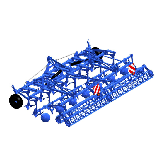
Design and function DESIGN AND FUNCTION Overview 1 Three-point tower 2 Frame 3 Tines 4 Working depth adjustment for tines 5 Automatic overload safety device for tines 6 Hollow discs (serrated) 7 Edge discs 8 Roller (double roller DRR 400/400) 9 Hydraulic transport lock 10 Feeler wheels 11 Drawbar... -
Page 36: Function
Design and function Function 5.2.1 Three-point tower The three-point tower with top link pin and drawbar comply optionally with cate- gory 3, 3N or 4N in accordance with ISO 730. Drawbar L3/Z3 complies with category 3. Drawbar L2/Z3 complies with category 3N. Drawbar L3/Z4 complies with category 4N. -
Page 37: Automatic Overload Safety Device For The Tines
Design and function 5.2.5 Automatic overload safety device for the tines The automatic overload safety device for the tines protects the frame and the tines from overload. The spring of the overload safety device has been preset. This set- ting must not be changed. 5.2.6 Hollow discs The hollow discs protected by shear bolts are serrated and level the soil behind the tines. -
Page 38: Lighting System
Design and function 5.2.12 Lighting system The lighting system contributes significantly to increasing the safety of the imple- ment in road traffic. -
Page 39: Preparation Of The Tractor
Preparation of the Tractor PREPARATION OF THE TRACTOR Tyres The pressure - especially in the rear tractor tyres - must be equal. In heavy condi- tions it may be necessary to add wheel weights and/or water ballast. (See manu- facturer’s instructions). Lift Rods Adjust lift rods to equal length. -
Page 40: Required Hydraulic Equipment
Preparation of the Tractor Required hydraulic equipment The device is supplied as standard with separate hydraulic connections for each consumer. The protective caps for the hydraulic connections are colour-coded and the hydraulic connections themselves are alphanumerically coded. For operation of the individual hydraulic devices listed below, the tractor must be equipped with the following double-acting control units: Tractor/Device Single-acting... -
Page 41: Three-Point Linkage
Preparation of the Tractor Three-point linkage Danger to life if three-point linkage category is too small If a drawbar or a top link pin is used with a category that is too small, these components may be overloaded and break. As a re- sult, the implement may fall down and injure or kill people in the DANGER immediate vicinity. - Page 42 Preparation of the Tractor For this implement, the only drawbars (1) and top link pins (2) approved are those listed in the table below and those that cor- respond to the category of the three-point linkage on the tractor. If they do not match, then either the tractor's three-point linkage or the implement's drawbar (1) and the top link pin (2) must be replaced with a suit-...
-
Page 43: Hydraulic System
Preparation of the Tractor Hydraulic system 6.7.1 Transport Lowering the three-point linkage CAUTION The device may be damaged if the three-point linkage of the trac- tor is lowered due to an incorrect setting or operation. For transport always switch the hydraulic system of the tractor to "position control". -
Page 44: Coupling And Uncoupling Implement
Coupling and uncoupling implement COUPLING AND UNCOUPLING IMPLEMENT Risk of injury when coupling the device WARNING There is a risk of body parts being crushed between the tractor and device The tractor must be secured against unintentionally rolling away. Never actuate the hydraulic system of the tractor if there are people between the tractor and device. - Page 45 Coupling and uncoupling implement Danger to life due to unsecured connection between lower link and drawbar If the connection between lower link and drawbar is not secured, the pintle of the drawbar may slip out. DANGER As a result, the implement may fall down and injure or kill people in the immediate vicinity.
-
Page 46: Coupling
Coupling and uncoupling implement Coupling When coupling the implement, switch the hydraulic system of the tractor to po- sition control. Drive the tractor backwards towards the implement until the tractor is in front of the implement and the catch hooks of the lower links (2) can be coupled with the drawbar (3). - Page 47 Coupling and uncoupling implement Secure the top link pin (7) using the linch pin. Lift out the implement all the way. Fold in the side parts. See also section entitled “Folding in the side parts”. If the drive to the field is via public high- ways, attach the protective devices.
-
Page 48: Dismounting
Coupling and uncoupling implement Dismounting Remove the protection devices. Lower the extended implement. To depressurise the hydraulic hoses, move the levers for the control units to the "float position". Actuate the hydraulic system on the trac- tor until the upper control link pin (7) is relieved. -
Page 49: Drawbar
Coupling and uncoupling implement Drawbar The drawbar (1) can be mounted on the device at two heights = draw point posi- tions. The picture shows the drawbar (1) in the upper mounting position = low draw point. The bores (2) are used to hold the drawbar (1) in the lower mounting position = high draw point. -
Page 50: Upper Control Link
Coupling and uncoupling implement Upper control link Risk of injury from unsecured upper control link pin If the upper control link pin is not secured, it may slip out or get CAUTION lost. As a result, the implement may fall down or be damaged. ... -
Page 51: Safety Equipment
Safety equipment SAFETY EQUIPMENT General information Before each use, the function of all safety equipment must be checked and it must be used or operated as specified in this manual. Protective devices WARNING Risk of injury Other road users could be injured by the tines. ... - Page 52 Safety equipment Secure the rear protective device using the tightening straps (4). Plug the connectors for the front bound- ary lights power supply into the corre- sponding sockets at the front on the im- plement. When working, the transport protection can be positioned on the frame in the flat steel bars and secured using the tightening straps.
-
Page 53: Transport Dimensions
Safety equipment Transport dimensions Before transportation on public highways, ensure that the maximum permitted di- mensions of 3 m transport width 4 m transport height are not exceeded. If fitted, swivel the edge discs backwards into the transport position. See section entitled "Edge discs". -
Page 54: Retracting/Extending The Side Sections
Retracting/extending the side sections RETRACTING/EXTENDING THE SIDE SECTIONS Risk of accident due to incorrect retraction of the side sections Incorrect retraction of the side sections will result in accidents if the- re are people in the slewing and folding area of the side section or if there are high-voltage lines in the slewing and folding area of the DANGER side sections. -
Page 55: Retracting
Retracting/extending the side sections Retracting Before retracting the side sections (1), lift out the device all the way. Retract the side sections (1) of the im- plement. This is done by operating the control unit in the retract position (1. pressure position). The side parts are retracted through the folding cylinder (2) up to the end position. -
Page 56: Extending
Retracting/extending the side sections Extending Risk of accident due to incorrect extension of the side sec- tions Incorrect extension of the side sections will result in accidents if there are people in the hazardous areas of the side section or if there are high-voltage lines in the slewing and folding area of the side sections. - Page 57 Retracting/extending the side sections Remove the protective devices with lighting. Before extending the side sections (1), lift out the implement all the way. Release the control unit of the tractor for the folding cylinders (2). Then switch the control unit to the retract position (1st pressure position) and then quickly to the extend position (2nd pres- sure position).
-
Page 58: Adjustments
Adjustments ADJUSTMENTS Risk of accident when making adjustments When making any adjustments to the device, there are risks of crushing, cutting, clamping and striking your hands, feet and body on heavy and occasionally compressed and/or sharp-edged parts. Always park implement on the ground. DANGER ... -
Page 59: Working Depth Of Tines
Adjustments 10.1 Working depth of tines 10.1.1 General information The working depth of the implement can be adjusted by approx. 5 to 25 cm. A precision adjustment can be made using the adjustment devices (1) with adjustment stops (2) and spacer plates (6). A rough setting can be conducted through shifting the adjustment stops (2) on the strut (3) with the aid of linch pins (4). -
Page 60: Hydraulic Working Depth Adjustment
Adjustments 10.1.2 Hydraulic working depth adjustment In the hydraulic working depth adjustment the adjustment stops (2) are used to set the maximum required working depth and the counter stop (9) is used to set the mi- nimum required working depth. The hydraulic cylinders -see arrow- are used to set either the maximum or mini- mum working depth adjustment as re-... - Page 61 Adjustments Use spacer plates to compensate for any gap (12) between the counter stop (9) and stop (7). Fix the counter stop (9) with the linch pin (4) and secure the linch pin (4).
-
Page 62: Feeler Wheel
Adjustments 10.3 Feeler wheel Risk of injury due to unsecured feeler wheel If the guide pin and cam lever are simultaneously removed, the WARNING feeler wheel is no longer held in place and can slide downwards when unsecured. This can result in crushing and foot injuries. ... -
Page 63: Working Depth Of Hollow Discs
Adjustments 10.4 Working depth of hollow discs Loss of components DANGER If the guide pins are not secured, they can fall out due to vibra- tions in operation. This can result in components being lost during operation and transportation and can cause accidents or damage to the implement and the tractor. -
Page 64: Working Depth Of The Edge Discs
Adjustments 10.5 Working depth of the edge discs Loss of components DANGER If the guide pins are not secured, they can fall out due to vibra- tions in operation. This can result in components being lost during operation and transportation and can cause accidents or damage to the device and the tractor. -
Page 65: Share Position
Adjustments 10.6 Share position WARNING Risk of injury due to removed shear bolt If the shear bolt is removed, the tine can pivot freely. This can lead to crushing of the fingers around the tine carrier. Replace a removed shear bolt immediately. The share position or the contact angle of the tines (1) can be altered. - Page 66 Adjustments A "steep" share position ensures that the tines (1) achieve good penetration even in hard and dry soils. The share position is altered by inserting the shear bolt (2) in a different position. Flat share position Insert the shear bolt through the hole (4) of the tine carrier (3) and the hole (5) of the tine (1).
- Page 67 Adjustments The adjustment has to be made for all the tines. Raise the attachment by a few centime- tres. Loosen and remove nut from the shear bolt (2). Press out the shear bolt using a suitable tool. ...
-
Page 68: Automatic Overload Protection
Adjustments 10.7 Automatic overload protection 10.7.1 Tines Risk of fatal injury due to high spring force If the tine, the hollow disc or the edging disc is actuated and has DANGER still not been moved back into the working position, it can sud- denly rebound into the working position with great force and at high speed. -
Page 69: Hollow Discs
Adjustments 10.7.2 Hollow discs Risk of fatal injury due to high spring force If the tine, the hollow disc or the edging disc is actuated and has DANGER still not been moved back into the working position, it can sud- denly rebound into the working position with great force and at high speed. -
Page 70: Edge Discs
Adjustments 10.7.3 Edge discs Danger to life due to high spring energy If the tine, the hollow disc or the edge disc is actuated and has still DANGER not been moved back into the working position, it can suddenly rebound into the working position with great force and at high speed. -
Page 71: Rollers
The rollers control the implement at the working depth. Irrespective of the roller type used, the soil is more or less recompacted or more or less crum- bled. Roller type Kristall 9 U Kristall 9 K U Tube bar roller RSW 540 RSW 600 Double roller... -
Page 72: Blade Rollers
Adjustments 10.8.2 Blade rollers CAUTION Loss of components If the guide pins are not secured, they can fall out due to vibra- tions during operation. The guide pins must always be secured by split rings. Working depth of blades The working depth of the blades (6) is ad- justed using the guide pins (3) as follows: ... - Page 73 Adjustments Movement of blades The upward movement of the blades (6) is limited using the guide pins (5). If neces- sary, slight movement upwards can be per- mitted. Position of blades The blades are generally screwed onto the blade frame (7) in the front position. In ca- se of wear, the blades (6) can be moved backwards.
-
Page 74: Pressure Load On Rollers - Intake Behaviour
Adjustments 10.8.3 Pressure load on rollers - Intake behaviour The pressure load on the rollers is determined by the position of the upper control link and the mounting position of the drawbar. The hydraulic system of the tractor must be switched to the float position. Drawbar The drawbar should always be mounted in the upper mounting position. - Page 75 Adjustments The lower the upper control link is mounted on the implement's three-point tower, the greater the pressure load on the rollers – resulting in better intake be- haviour. The higher the upper control link is mounted on the implement's three-point tower, the lower the pressure load on the rollers –...
- Page 76 Adjustments Upper control link mounting position Risk of injury from unsecured upper control link pin If the upper control link pin is not secured, it may slip out or get lost. CAUTION As a result, the implement may fall down or be damaged. As a result, people in the immediate vicinity may be injured.
- Page 77 Adjustments Drawbar mounting position The mounting position of the drawbar (1) with unhitched implement can be changed as follows: Remove the nuts (3) on the bolts (4) of the two locking pieces (5). Pull the drawbar (1) as far as the middle out of the bores of the rail plates (6).
- Page 78 Adjustments Push the locking pieces (5) onto the drawbar (1). Ensure that the side with the support surface (7) is facing the rail plate (6). Push the drawbar (1) through the bores until the two ends of the drawbar (1) on the left and right are the same distance from the rail plates (6).
-
Page 79: Turning At The Headland
Adjustments 10.9 Turning at the headland DANGER Risk of damage to components If the implement is not fully raised, there is a danger that compo- nents may be damaged during an improper turn at the headland. Before turning at the headland the implement must be completely raised before turning-in to avoid any damage to the implement. -
Page 80: Switching Over To Different Share Systems
Switching over to different share systems SWITCHING OVER TO DIFFERENT SHARE SYSTEMS Danger presented by implement not secured against lowering DANGER If the raised implement is not secured to prevent it from lowering, people underneath may be injured or killed. A raised implement must be supported when people are carrying out maintenance or service work in its danger zone. -
Page 81: Tine With Integrated Share Foot
Switching over to different share systems 11.2 Tine with integrated share foot To switch over to a different share system, the corresponding components of the tine (1) must be removed and replaced with the components required for the de- sired share system. ... -
Page 82: Tines With Quick-Change System
Switching over to different share systems 11.3 Tines with quick-change system Risk of accident due to falling and extending of components and implements Performing work under raised components/implements or next to WARNING swivelled-in components/implements is dangerous. Always secure the tractor against rolling away. ... -
Page 83: Removing The Share Base
Switching over to different share systems 11.3.1 Removing the share base When the implement has been lifted out, it must be secured with the aid of a suitable support to prevent it from unintentionally dropping. Switch the tractor's three-point linkage hydraulic system to position control. -
Page 84: Attaching The Share Base
Switching over to different share systems 11.3.3 Attaching the share base The share base (2) is attached to the tine (1) in reverse order to its removal. When the implement has been lifted out, it must be secured with the aid of a suitable support to prevent it from unintentionally dropping. -
Page 85: Switching Off The Device
Switching off the device SWITCHING OFF THE DEVICE 12.1 Shutting down the device in an emergency In an emergency shut down the device via the tractor. Switch the tractor engine off. Remove the ignition key. Damage caused by improper storage of the device If incorrectly or improperly stored, the device may be damaged, CAUTION e.g. -
Page 86: Maintenance And Repairs
Maintenance and repairs MAINTENANCE AND REPAIRS 13.1 Special safety instructions 13.1.1 General Risk of injury when carrying out maintenance and repair work There is always the risk of injury when carrying out maintenance and repair work. WARNING Use suitable tools, suitable climbing aids, platforms and support elements. -
Page 87: Immobilise The Implement For Maintenance And Repairs
Maintenance and repairs 13.1.4 Immobilise the implement for maintenance and repairs Risk of accidents when tractor starts up Injuries may occur if the tractor starts moving during maintenance and repair work. Switch off the tractor engine before carrying out any work on the WARNING implement. -
Page 88: Working Under The Raised Device
Maintenance and repairs 13.1.7 Working under the raised device Risk of accident due to lowering and extending of compo- nents and devices It is extremely dangerous to work under raised or next to retracted WARNING components and devices. Always secure the tractor to prevent it from rolling away. Re- move the ignition key and secure the tractor to prevent it from being started up by unauthorised persons. -
Page 89: Environmental Protection
Maintenance and repairs Risk of accident due to tool slipping off If applying a large force, e.g. when loosening bolts, the tool may WARNING slip off. This may result in hand injuries on sharp-edged parts. Avoid applying a large force by using suitable auxiliary equip- ment (e.g. -
Page 90: Lubrication
Maintenance and repairs 13.3 Lubrication Eye injuries due to grease WARNING When lubricating the lubrication points, grease can escape be- tween components at high pressure and cause injury to the eyes. In case of injury, seek medical attention immediately. Wear protective clothing during lubrication, particularly goggles. ... -
Page 91: Lubrication Chart
Maintenance and repairs 13.3.1 Lubrication chart For all lubrication work use the high-grade grease Olistamoly 2 or an equivalent high-grade grease only. Item no. Designation Quantity 877 1620 Grease cartridge Olistamoly 2 400 g 877 1581 Grease Olistamoly 2 18 kg Item Number of Every 50... -
Page 92: Maintenance Intervals
The hydraulic hoses must be replaced at the latest 6 years after the date of manufacture. Use hydraulic ho- ses authorised by LEMKEN only. Safety equipment Check that the safety equipment functions properly. -
Page 93: Weekly Inspection
Maintenance and repairs 13.4.3 Weekly inspection Check What to do? Wheel nuts Check that all wheel nuts are tight and, if re- quired, retighten the wheel nuts to the appro- priate torque. Screw connections Retighten all other bolts and nuts on the device to the appropriate torque. -
Page 94: Tightening Torques
Maintenance and repairs 13.5 Tightening torques 13.5.1 Wheel nuts Diameter / Tightening tor- Thread [Nm] M12x1.5 M14x1.5 M18x1.5 M20x1.5 M22x1.5 13.5.2 Other screw connections Diameter / Strength - Strength cate- Strength - Thread category 8.8 gory 10.9 [Nm] category 12.9 [Nm] [Nm] 13,6... -
Page 95: Checking Connections To The Tractor
Maintenance and repairs 13.6 Checking connections to the tractor Visually inspect the hydraulic couplings. Check that the hydraulic couplings are not leaking hydraulic fluid. Connect the hydraulic lines to the tractor and check for leaks under pressure. Defective or leaking couplings must be repaired or replaced immediately by a specialist workshop. -
Page 96: Air Pressure Of Tyres
Maintenance and repairs 13.7 Air pressure of tyres WARNING Hazard due to incorrect air pressure Excessive air pressure in the tyres can cause the tyres to burst. Insufficient air pressure can cause overloading of the tyres. The following minimum and maximum permitted air pressures are approved, de- pending on the tyre size, the profile and the PR figure or the load index. -
Page 97: Trapezoidal Packer Roller Scrapers
Maintenance and repairs 13.8.2 Trapezoidal packer roller scrapers The trapezoidal packer roller is fitted with scrapers (1) whose distance from the roller casing (4) can be adjusted with eccentric nuts (2). Undo the bolt (3) of the eccentric nut (2) using a 19 mm spanner. -
Page 98: Technical Data
Technical Data TECHNICAL DATA Kristall 9 400 K 400 KU 500 K 500 KU 600 K 600 KU Weight without roller 1,861 2,328 1,445 1,776 1,543 1,901 approx. [kg] Weight with knife roller 2,941 3,408 2,205 2,536 2,459 2,817 MSW 600 approx. [kg] Length with knife roller MSW 600 approx. -
Page 99: Identification Plate
Identification plate IDENTIFICATION PLATE The identification plate (1) is situated on the front of the frame. -
Page 100: Noise, Airborne Sound
Noise, Airborne Sound NOISE, AIRBORNE SOUND The noise level of the implement does not exceed 70 dB (A) during work. NOTES As the version of equipment is depending from the order, the equipment of your implement and its description concerned may deviate in some cases. To ensure a continuously updating of the technical features, we reserve the right to modify the design, equipment and technique. -
Page 101: Index
Index INDEX Air pressure ......................94 Axle loads ......................24 Blade rollers......................70 Check Chains ....................... 37 Coupling ....................... 44 Drawbar ........................ 47 Extending......................54 Feeler wheel ......................60 Hollow discs......................61 hydraulic equipment ..................... 38 MAINTENANCE ....................84 Overload protection ....................66 Power sources...................... -
Page 102: Eu Declaration Of Conformity
Weseler Strasse 5 D-46519 Alpen, Germany hereby declare that the implement described below Cultivator Kristall 9 K / KU ___ ___ ___ ___ ___ ___ Model Serial number in the plant shipped equipment scope, complies with the pertinent regulations of EU Directive for Machines 2006/42/EG.
Need help?
Do you have a question about the Kristall 9 K and is the answer not in the manual?
Questions and answers