
Related Manuals for Donaldson DFPRE 4L


Summary of Contents for Donaldson DFPRE 4L
- Page 1 INSTALLATION, OPERATION AND MAINTENANCE MANUAL DFPRE™ Dust Collectors Series DFPRE Large 4L - 6L - 9L - 12L Publication DOCAM1216501 REV 01 (GB) 1121 MASTER LANGUAGE - ENGLISH...
-
Page 2: Table Of Contents
Installation, Operation and Maintenance manual DFPRE Large Dust Collectors TABLE OF CONTENTS MPORTANT ..........................4 Applications having a risk of sparks and fires ..............4 GENERAL SAFETY REQUIREMENTS................... 5 INSTALLATION ..........................8 Required tools and equipment .................... 8 Delivery and inspection ....................... 8 Location considerations ....................... - Page 3 Installation, Operation and Maintenance manual DFPRE Large Dust Collectors LIST OF FIGURES Figure 1: DFPRE dust collector. Model DFPRE 9L Standard illustrated ......7 Figure 2: Four-point lifting arrangement................10 Figure 3: Fork lifting arrangement ..................10 Figure 4: Lifting ........................10 Figure 5: Typical foundation anchor ..................11 Figure 6: Removal lifting profiles ..................
-
Page 4: Mportant
Installation, Operation and Maintenance manual DFPRE Large Dust Collectors MPORTANT Please read this manual carefully before installation. This manual should be read in conjunction with the respective controller manual supplied with the dust collector. Product reliability, warranty and safe operation may be compromised by not following the guidance given in these documents. -
Page 5: General Safety Requirements
Delivery is an integral part of the manual. Other items of equipment, not supplied under the Scope of Delivery from Donaldson, should be installed, operated and maintained according to the documentation supplied with the respective equipment. Any modification carried out on the ‘as supplied’ equipment may reduce reliability and safety, and will nullify warranty;... - Page 6 Installation, Operation and Maintenance manual DFPRE Large Dust Collectors Where necessary for safety, the dust collector is fitted with safety guards. Removal of these guards and any subsequent work should only be carried out after adequate precaution is taken to ensure it is safe to do so. All guards should be refitted before re-energising.
-
Page 7: Figure 1: Dfpre Dust Collector. Model Dfpre 9L Standard Illustrated
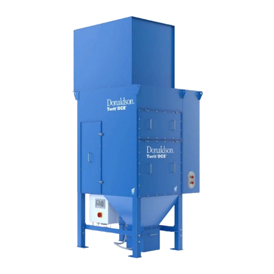
Installation, Operation and Maintenance manual DFPRE Large Dust Collectors Lifting lugs for fan Fan box Lifting bracket for unit Slide gate handle Dirty air inlet Clean air plenum access door Dirty air plenum access door Hopper Powerbox 200 L dust drum Earthing point Figure 1: DFPRE dust collector. -
Page 8: Installation
This can be achieved by applying a continuous 5 mm bead of sealing compound to the mounting surface, along each side of the hole pattern. For non-Donaldson equipment please also check supplier’s IOM manual for any specific requirements. -
Page 9: General Guidance To Lifting
Snow and wind loads on outside installations. For collector weights and dimensions refer to the datasheet, publication number DOCAM1382701 (DFPRE 4L and 6L) or DOCAM1449401 (DFPRE 9L and 12L). General guidance to lifting The collector should be lifted using either the four-point lifting arrangement or the fork-lifting arrangement by a qualified competent person (refer to figures 2 and 3). -
Page 10: Figure 2: Four-Point Lifting Arrangement
Installation, Operation and Maintenance manual DFPRE Large Dust Collectors ≤ 90° Figure 2: Four-point lifting arrangement Figure 3: Fork lifting arrangement Figure 4: Lifting... -
Page 11: Positioning The Collector
Installation, Operation and Maintenance manual DFPRE Large Dust Collectors Positioning the collector Lift the collector into position following the general guidance to lifting. Take care not to damage dust container and cables when using fork lifting method. 2. Using spirit levels, line up both horizontally and vertically, using shims where required. -
Page 12: Cyclopeel / Spark Trap Assembly
Installation, Operation and Maintenance manual DFPRE Large Dust Collectors Cyclopeel / spark trap assembly For collectors supplied with a cyclopeel pre-separator or a spark trap: Refer also to figure 7 . Remove one column of filter cartridges from right-hand side of collector. 2. -
Page 13: Dust Container Assemblies
Installation, Operation and Maintenance manual DFPRE Large Dust Collectors Figure 8: Fan box assembly Dust container assemblies Apply a continuous 5 mm bead of sealing compound to mounting surface of dust container, along eacht side of the bolt pattern. 2. Bolt dust container to the hopper flange. Keep your toes, and feet away from pinch points giving your full attention while assembling dust disposal system. -
Page 14: Figure 10: Big-Bag
Installation, Operation and Maintenance manual DFPRE Large Dust Collectors When using rotary airlock or screw conveyor: • A sealant must be fitted between all connecting flanges. • Check the rotation (direction of the arrow). • Electrical connections shall be made by a qualified electrician. hopper transition piece bolt / washer / nut... -
Page 15: Compressed Air Requirements
It is a requirement of the Supply of Machinery (Safety) Regulations 2008 to provide adequate isolation and emergency stop facilities. Due to the varied nature of site installations this cannot be provided by Donaldson but instead is the responsibility of the customer. -
Page 16: Overload Protection
It is a requirement of the Supply of Machinery (Safety) Regulations 2008 to provide adequate isolation and emergency stop facilities. Due to the varied nature of site installations this cannot be provided by Donaldson but instead is the responsibility of the customer. -
Page 17: Figure 13: Earthing Location
Installation, Operation and Maintenance manual DFPRE Large Dust Collectors This way the dust will not penetrate the media and can be cleaned off as described above. After the elements are conditioned the slide gate can be placed back to its original position (STAGE 2 and 3). ... -
Page 18: Start-Up Sequence
Installation, Operation and Maintenance manual DFPRE Large Dust Collectors Start-up sequence Turn on compressed air supply. 2. Check that the compressed air supply is maintained at the recommended pressure. 3. Adjust the slide gate as described in commissioning. 4. Switch on controller. Shut-down sequence At the end of any period of operation it is most important that all residual deposits are cleared from the filter cartridges, casing, and discharge hopper. -
Page 19: Operation
Installation, Operation and Maintenance manual DFPRE Large Dust Collectors OPERATION On installations where the inlet duct is relatively short, this procedure may result in a dust emission occurring at the inlet and therefore may not be an appropriate procedure if the dust being handled is dangerous. Therefore a Risk Assessment must be carried out to ensure the final procedure is safe. -
Page 20: Dust Disposal
Installation, Operation and Maintenance manual DFPRE Large Dust Collectors Dust disposal For safe handling of the dust container an assessment must be made to satisfy the requirements of the European Directive 90/269/EEC on manual handling of loads. Dust containers may require regular emptying. Dust containers should securely replaced and resealed prior to collector restart. -
Page 21: Maintenance
Ensure the pneumatic system is fully isolated and depressurized before any work is carried out. For ancillary equipment not manufactured by Donaldson, refer to manufacturer’s instructions. If it is unavoidable to work on the equipment while a potentially explosive atmosphere is present, care should be taken to avoid introducing ignition sources not present during expected operation. -
Page 22: Routine Inspection
Installation, Operation and Maintenance manual DFPRE Large Dust Collectors Routine inspection To maintain the optimum performance of the dust collector, a routine inspection should be made to minimise down-time in the event of equipment malfunction, particularly on continuous performance applications and to ensure the equipment is maintained to its original supply condition. - Page 23 Installation, Operation and Maintenance manual DFPRE Large Dust Collectors Weekly Open valve at the bottom of moisture separator bowl and allow collected water to drain off, then close valve. 2. Check the pressure drop across the filter by viewing the display on the front panel of the controller.
-
Page 24: Figure 15: Dirty Air Plenum Access Cover Gasket
Installation, Operation and Maintenance manual DFPRE Large Dust Collectors 4. If applicable, check collector earthing continuity. 5. If applicable, check measures taken to avoid ignition sources are still in place. 6. Open the clean air chamber access cover and, by looking through fan inlet eye, inspect fan thoroughly. -
Page 25: Valve Disassembly / Reassembly
Installation, Operation and Maintenance manual DFPRE Large Dust Collectors Figure 16: Clean Air Plenum access cover gasket Valve disassembly / reassembly Do not overtighten pipe connections. Refer also to figure 9. Switch off the compressed air. Make sure manifolds are depressurized before any work is carried out. 2. -
Page 26: Filter Cartridge Replacement
Installation, Operation and Maintenance manual DFPRE Large Dust Collectors Retainer clip* Coil Spring washer Solenoid base sub-assembly (torque to 20 Nm) Silencer* Spring* Bonnet screw Core assembly* Valve bonnet Diaphragm* Bleed hole Valve body Figure 17: Diaphragm valve *Included in diaphragm valve service kit Filter cartridge replacement All filter cartridges should be changed at the same time. - Page 27 Installation, Operation and Maintenance manual DFPRE Large Dust Collectors 6. Place cartridge into a sealable bag and dispose of the cartridge properly. If in doubt regarding safe disposal of used cartridges, consult your local regulations. Clean sealing surfaces with a damp cloth. Surface around opening on seal frame must be clean to ensure an airtight cartridge seal.
-
Page 28: Hepa Filter Replacement
Installation, Operation and Maintenance manual DFPRE Large Dust Collectors Dirty Air Plenum access door Cartridge suspension yoke Cartridge Cartridge cover Washer Wing nut Figure 18: Cartridge replacement HEPA filter replacement Remove the HEPA filter by unclamping the outlet grid panel at the side/top. 2. -
Page 29: Fan Assembly Removal
Installation, Operation and Maintenance manual DFPRE Large Dust Collectors Fan assembly removal Isolate electrical power supply. Open clean air chamber access door. 2. Disconnect electrical cables from terminal box. 3. Remove fan securing bolts. 4. Remove airflow damper panel or fan box from top of collector, if applicable. 5. - Page 30 Installation, Operation and Maintenance manual DFPRE Large Dust Collectors TABLE 1 – FAULT LOCATION Symptom Possible cause Action Part loss of Compressed air If compressor stopped, rectify compressor fault; check interlocks; suction malfunction. check motor and supply; check drive. (excessive If compressor OK, check pulses at manifold pressure gauge.
- Page 31 Installation, Operation and Maintenance manual DFPRE Large Dust Collectors TABLE 1 – FAULT LOCATION (CONTINUED) Symptom Possible cause Action Check motor supply overloads, fuses and interlocks (if fitted). Total loss of Fan motor stopped. suction. Check motor connections and windings. Check that dust container is not overfull.
-
Page 32: Specification
100 ms 51 liters per pulse Normal operating pressure. Recommended initial settings; these may be varied with experience. Sizes suitable for runs of pipe up to 30 m (100ft) in length; for longer runs consult with Donaldson. 1 bar = 10... - Page 33 Installation, Operation and Maintenance manual DFPRE Large Dust Collectors TABLE 4 – STANDARD FAN MOTOR SUPPLY VOLTAGE DETAILS To comply with European standards the motor nameplate will display the following: 3 Phase / 50 Hz (IEC 60034-30) Nameplate details Range 230/3/50 D 220-240 D 0.75 –...
-
Page 34: Spare Parts List
Installation, Operation and Maintenance manual DFPRE Large Dust Collectors SPARE PARTS LIST Description Part number Filter cartridge assembly CARTRIDGE DFE ULTRA-WEB OD (349 X 349) MM X L 660 MM Ultra-Web 2626827-000-440 ® TRIAGONAL CARTRIDGE DFE ULTRA-WEB OD (349 X 349) MM X L 660 MM Ultra-Web Earthed ®... - Page 35 FR 501 fan assembly (including motor†), 18.5 kW, 400V/690V, 50Hz 8PPAM0258600 ART 632 fan assembly (including motor†), 22.0 kW, 400V/690V, 50Hz 8PPAM0258700 For other types/specifications/motors for hazardous areas consult Donaldson † Access door assembly GASKET PRIK 5004 EPDM SHEET THICKNESS 1 MM TO...
Need help?
Do you have a question about the DFPRE 4L and is the answer not in the manual?
Questions and answers