
Related Manuals for Atlantic Boilers GWR 9


Summary of Contents for Atlantic Boilers GWR 9
- Page 1 ATLANTIC 2000 PO Box 11 Ashton Under Lyne OL6 7TR +44. (0) 161 621 5960 Fax +44. (0) 161 621 5966 info@atlantic2000.co.uk www.atlanticboilers.com T30.05477.07...
-
Page 2: Table Of Contents
CONTENT - PRESENTATION ........................... 3 - DESCRIPTION ............................3 - RANGE ..............................3 - TECHNICAL SPECIFICATIONS ......................4 - CHARACTERISTICS ..........................4 - ELECTRICAL CHARACTERISTICS...................... 4 - PIPE CONNECTION DIAMETERS......................5 - DIMENSIONS ............................5 - DESCRIPTION OF THE COMPONENTS ..................... 6 - CIRCULATING PUMP CHARACTERISTICS .................. -
Page 3: I - Presentation
Radiators 400 V. Tri GWR 9 35 < T°C < 85 230 V.mono Low temperature 400 V. Tri GWR 9 BT 20 < T°C < 55 Radiators GWR 18 400 V. Tri 35 < T°C < 85 Low temperature GWR 18 BT 400 V. -
Page 4: Technical Specifications
II - TECHNICAL SPECIFICATIONS 1 - CHARACTERISTICS Models GWR 9 GWR 18 Ex factory power max.i 12 ≤ P ≤ 18 6 ≤ P ≤ 9 1) refer to § 2 - below Adjustable power Heating system working pressure min. -
Page 5: Pipe Connection Diameters
TECHNICAL SPECIFICATIONS 3 - PIPE CONNECTION DIAMETERS Models GWR 9 GWR 18 Ø Heating flow/return inches Ø Valve evacuation 16/18 4 - DIMENSIONS Fig. 1... -
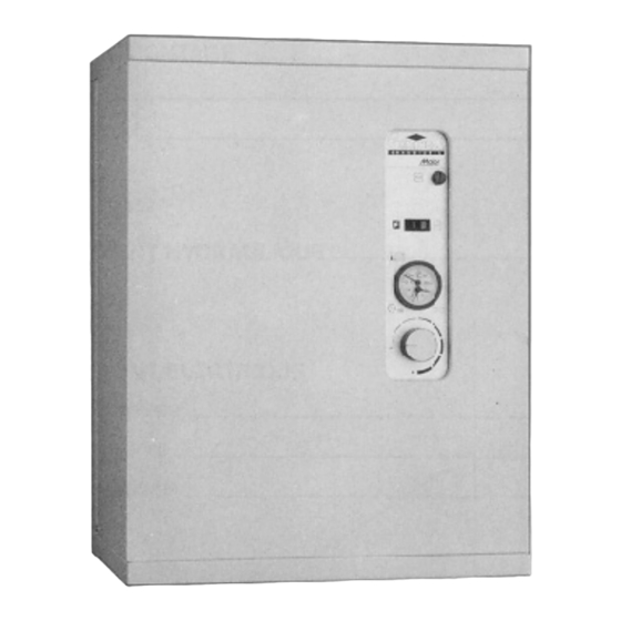
Page 6: Description Of The Components
TECHNICAL SPECIFICATIONS 5 - DESCRIPTION OF THE COMPONENTS Fig. 2 1) Electrical resistances cover 14) Contactors 2) Thermomanometer 15) Electrical connection terminals 3) Control panel on hinge 16) Connection terminal for clock, thermostat and load shedding 4) On/Off switch 17) Screw for removing the boiler from its bracket 5) Temperature control button 18) Electric heat exchanger insulator 6) Control panel latch screw... -
Page 7: Circulating Pump Characteristics
TECHNICAL SPECIFICATIONS 6 - CIRCULATING PUMP CHARACTERISTICS The circulating pump is equipped with a 3-speed motor with a maximum input power of 88 W. The electrical power consumption of the heating cir- culating pump can be greatly optimised by adapting the speed to the requirements of the installation by using the optional control devices proposed (section... -
Page 8: Operation
9) Circulating pump 5) Bleeds 10) 12 L expansion vessel GWR 9 boilers only have a single sheath receiving - If the power requested is 15 kW the heating elements (7, fig. 5). (12 kW < P < 18 kW) ( = cold outside temperature) •... -
Page 9: Installation
IV - INSTALLATION 1 - GENERAL These rules are specific to the buildings in which the devices are installed. The installation and servicing of the boiler must be carried out by a qualified professional person in ac- cordance with the regulations and good trade prac- tice in force for the country in which the boiler is installed, particularly (non-exhaustive list): 1.1 - Regulatory conditions for installation... -
Page 10: Assembly
INSTALLATION 2 - ASSEMBLY Before any intervention, cut off the - Remove the cover after removing the two screws power supply. located in the lower part of each side of the boiler (C, fig. 6), The boiler must be installed in an area - Fit the attachment bracket (supplied with the boil- suitable for its protection index (IP x er) (4, fig. -
Page 11: Hydraulic Connection
- 10 - INSTALLATION 3 - HYDRAULIC CONNECTION In accordance with the decree of the • For an outlet at the bottom: Ministry of Health, the filling system of . elbow joint (A) will be positioned on the heat- the heating circuit must be fitted with a ing return of the boiler. -
Page 12: Flow/Pressure Curve
. 230 V single phase (GWR 9) used to make this connection must be in conform- . 400 V three-phase (GWR 9 and GWR 18) ity with the codes of practise in force . 230 V three-phase, please consult us, - the premises must be suitable in terms of boiler - Earth connection compulsory. -
Page 13: Power Reduction
(item 14) (refer to the table opposite and fig. 11) C + D +E - for the GWR 9, each link removed (C,D and/or F) After removing the links (C,D and/or E), you reduces the power by 1 kw... -
Page 14: Gwr 5 Internal Wiring
INSTALLATION 4.3 - GWR 9 internal wiring 4.3.1 - Schematic diagram Fig 13... - Page 15 - 14 - INSTALLATION 4.3.2 - Wiring diagram Fig 14...
-
Page 16: Gwr 16 Internal Wiring
INSTALLATION 4.4 - GWR 18 internal wiring 4.4.1 - Schematic diagram Fig 15... - Page 17 - 16 - INSTALLATION 4.4.2 - Wiring diagram Fig 16...
-
Page 18: Commissioning
V - COMMISSIONING 1 - PROTECTION OF THE INSTALLATION Atlantic 2000 recommends the use of the following heating system water conditioning products: - AL16 corrosion inhibitor (or equivalent products), 1.1 - AL16 AL16 is a non-toxic, biocide, traceable corrosion inhibitor specially designed to protect multi- metal heating circuits. -
Page 19: Filling The Installation With Water
COMMISSIONING 2 - FILLING THE INSTALLATION WITH WATER - Filling the installation: • close the filling valves, • open the heating flow/return valves, if neces- • check the leaktightness of the circuit, sary, • bleed the entire installation, particularly the ra- •... -
Page 20: Commissioning
COMMISSIONING 5 - COMMISSIONING Fig. 17 1) On/Off switch 2) Fuse 3) Thermomanometer 4) Temperature setting button - Switch on the general heating system switch, - switch the On/Off switch to On (1, fig. 17): • the LED lights up - set the aquastat button (4, fig. -
Page 21: Maintenance
VI - MAINTENANCE The annual inspection of the boiler and of the com- fying the type and serial number of the boiler. bustion product outlet is compulsory. It must be car- Before any servicing, cut the power sup- ried out by a qualified person. ply. -
Page 22: Operating Faults
The thermostats shut down the boiler if: the boiler temperature rises above 100°C (models GWR 9 and GWR 18). the boiler temperature rises above 95°C (models GW R 9 BT and GWR 18 BT) The boiler can be restarted: - by manual restarting or by the thermostat(s) (21). -
Page 23: Nomenclature
VIII - NOMENCLATURE GWR 9 / GWR 9 BT... - Page 24 - 23 - NOMENCLATURE...
- Page 25 NOMENCLATURE GWR 18 / GWR 18 BT...
- Page 26 NOMENCLATURE - 26 -...
Need help?
Do you have a question about the GWR 9 and is the answer not in the manual?
Questions and answers