Table of Contents
Advertisement
Quick Links
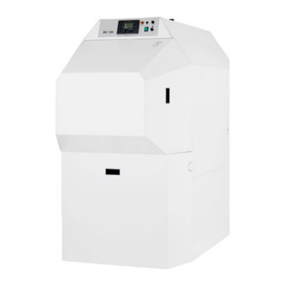
BK SERIES
YEAR ROUND MAXIMUM CONDENSING BOILER
burning diesel oil, kerosene, natural gas or liquid petroleum gas
90%
A
A
and above
86% - 90%
B
82% - 86%
C
78% - 82%
D
74% - 78%
E
70% - 74%
F
70%
G
Below
OPERATING & MAINTENANCE MANUAL
BK50 - BK70 - BK100
ATLANTIC 2000 - boilerplant sales ACM ATLANTIC - commissioning and maintenance ATLANTIC 4422 – spares
Atlantic 2000 Registered in England Company No: 1477687 Vat Reg No: 306 0653 89
PO BOX 11, ASHTON UNDER LYNE, OL6 7TR T: 0161 621 5960 E: technical@atlanticboilers.com www.atlanticboilers.com
Advertisement
Table of Contents

Related Manuals for Atlantic Boilers BK50


Summary of Contents for Atlantic Boilers BK50
- Page 1 70% - 74% Below OPERATING & MAINTENANCE MANUAL BK50 - BK70 - BK100 ATLANTIC 2000 - boilerplant sales ACM ATLANTIC - commissioning and maintenance ATLANTIC 4422 – spares Atlantic 2000 Registered in England Company No: 1477687 Vat Reg No: 306 0653 89...
-
Page 2: Table Of Contents
3.2.1 Risk of frost damage ����������������������� Terminal assignment and le- 3.2.2 Corrosion, boiler damage ���������������� gend to Conform 6.0 3.3 Norms, regulations ����������������������������� 8 3.4 Operation and monitoring ������������������� 8 Spare parts BK50, BK70 and 3.4.1 Burner faults/remote unlocking ������� BK100 3.4.2 Maintenance (servicing) ������������������ 3.5 Safety installations ����������������������������� 9 10 EC conformity certification 3.5.1 Water-side safety installations���������... -
Page 3: Overview - Laws, Regulations And Standards
BK50/BK70 BK100 Overview – laws, regulations and standards Overview – laws, regulations 92/42/EWG Efficiency guidelines and standards General information: 2006/95/EG Transportation, installation, mounting and electri- Electrical equipment designed for use within cer- cal connections should be done by a competent tain voltage limits person. He bears responsibility for a proper implementation of these works. DIN EN 267:2011-02 Fan-assisted oil burner Before installation of the Fully Condensing Boiler, it is necessary to obtain permission of the local DIN EN 676:2003 + A2:2008 heating equipment inspection board or other Automatic forced draught burners for gaseous competent authorities. fuels In order to prevent penetration of oxygen into the DIN EN 677:1998-08 closed heating system, it is advisable to perform... - Page 4 Overview – laws, regulations and standards DIN EN 304:2004/01 Condensing heating boilers – test code for hea- ting boilers with fan-assisted oil burners 1 BImSchV (22.03.2010) Regulation on small furnaces ATV A 251 Removal of condensate from chimneys DIN EN 60 335-1:2010 DIN EN 60 335-2-102:2010 Safety of household and similar electrical appli- ances 2004/108/EG Electromagnetic compatibility Furthermore, for installation in Austria the following norms and regulations are valid: • ÖVE – Rules and local rules • Art. 15a B-VG • FAnlG – Law on furnaces dated June 12, 2011...
-
Page 5: Information
CE0035CM103 Heating output 71 - 120 kW Flue gas temperature 47°C / 54°C Max. operation temperature 100°C UNIT BK50 fully condensing boiler with fan Max. operation overpressure 4 bar Water content 200 l Electrical connection 230 V~/50 Hz/480 W Product Id. Nr. -
Page 6: Important Information
Information 2.3 Important information 2.4 Validity These operating instructions are valid only with Information respect to the Fully Condensing Boiler marked with the production number (See Label). When Care should be taken to ensure that, depen- making requests and ordering spare parts, ple- ding on the fuel and boiler type, the approp- ase always state these model (factory) numbers! riate operating mode is selected (See Ope- These operating instructions contain information rating instruction for Conform 6.0 and Initial about the Fully Condensing Boiler and its items commissioning manual). Failure to comply of equipment, insofar as these belong to the with this provision will result in expiration of scope of delivery. Statements about equipment the guarantee on the boiler body! Without the not belonging to the scope of delivery are inten- submitted commissioning report, the guarantee ded purely for informational purposes. A legal agreement with the company shall not claim for this equipment (options) is excluded. enter into force. Should materials of the third-party manufacturers be attached to these operating instructions (ope- In order to prevent penetration of oxygen into rating instructions of third parties), so the the closed heating system, it is recommended company cannot assume any liability for their to perform system separation between the floor correctness, validity, technical data etc. heating and the heating system, by means of a heat exchanger. 2.5 Applicability 2.3.1 Updating service All information provided herein with respect to These operating instructions are not subject to... - Page 7 BK50/BK70 BK100 Information ◦ Installation and commissioning, ◦ Operation and monitoring, and ◦ Maintenance (servicing). • Defective installation works and/or defective electrical installation. • Chemical, electrochemical or electrical influ- ences. • For substantial third-party products, the liability of the company is limited to the assignment of liability claims to which the company is entitled against the supplier of the third-party products. Attention Prior to each commissioning and maintenance cycle, the furnace should be checked for gas side malfunctions and leakproofness.
-
Page 8: Safety Instructions
Safety instructions Safety instructions The operating instructions should be positioned visibly adjacent to the Fully Condensing Boiler. 3.1 General information The connection and adjustment of the heating These operating instructions are valid exclusively system should be performed by a qualified plum- for the the Fully Condensing Boiler. The staff ber. The heating technician should familiarize the in charge of installation, commissioning or main- operator(s) of the Fully Condensing Boiler with tenance should read the operating instructions its functions and servicing! In the event of any prior to starting these works. The requirements faults or disturbances in the operation of the Fully contained in these operating instructions must Condensing Boiler, please notify the heating ins- be adhered to. In the event of a non-compliance tallation company! with the operating instructions, the guarantee claim vis-à-vis the company shall expire. If you smell gas, there is a risk of explosion 3.2 Safety guidelines • Avoid open fire and spark formation (for example when turning on and out lights and Attention electrical appliances) -
Page 9: Risk Of Frost Damage
BK50/BK70 BK100 Safety instructions combustion, under assistance of a specialized installing company. If, after a cleaning, repeated dust exposure shall still be possible, (for example, due to spongy chimney joints), take the appropriate measures (for example, clean the chimney). Modification of the gas heating system The operator may under no circumstances make changes in the heater, pipes for gas, electricity, water, air supply and flue gas. These works may be performed only by a hea- ting technician, to eliminate the above mentioned hazards. 3.3 Norms, regulations • The boiler must be serviced in regular inter- vals. We recommend to conclude, for this purpose, a maintenance contract. Fig. 1: A lateral distance of minimum 600 mm should be maintained either on the left or on the right side • The Fully Condensing Boilers may be ins- of the boiler. talled and operated only in the boiler and installation rooms as required by local regu- A connecting line should be lead to the chimney lations and guidelines (FeuAO) with respect as short as possible and ascending. This is the to furnaces. only way to ensure the optimum performance. The pipes should be carefully sealed! If the • For Austria are also relevant the provisions... -
Page 10: Burner Faults/Remote Unlocking
Safety instructions functions and to check the tightness of the Fully the power supply and only by a skilled electri- Condensing Boiler and its connections. cian. Before commencement of any works on the Attention electrical equipment, make sure that the voltage is completely switched off. Damaged, burned, In the event of unusual operating performance frayed cables as well as loose and untight cable in the functioning of the Fully Condensing connections must be immediately replaced by a Boiler, for example, malfunctions or faults in skilled electrician. energy supply, the unit must be immediately In the event of a defective fuse, they must be shut off. replaced only with the original fuses with prescri- bed amperage. Determine the cause of the problem or fault and fix it in a safe and secure manner. Start re- 3.5 Safety installations commissioning only after complete elimination of faults. Attention 3.4.1 Burner faults/remote unlocking The commissioning of the Fully Condensing In case of a burner defect or fault, the red push Boiler without a properly functioning safety button in the control panel will flash. Press the installation (or with an improperly functioning button shortly to unlock the burner. Should the safety installation), is not permitted. burner fault reappear, call a qualified specialist. 3.5.1 Water-side safety installations Safety installations pursuant to DIN 12 828 such as the safety valve, safety temperature limiter... -
Page 11: Waste Disposal And Environmental
BK50/BK70 BK100 Safety instructions fuels that are indicated in the order confir- non-recyclable residues should be disposed of mation may be used as working materials. pursuant to the German Waste Management Law The definition is made in compliance with 1. (AbfG). BImSchV (1st Federal German ruling on emissi- During disposal works, use safety gloves. ons control) condensing boilers: these are heat generators which utilize by condensation, as a result of their design, the heat of vaporization of water vapour contained in flue gases. This defini- tion differentiates the heat generation with utiliza- tion of the heat of vaporization of water vapour in flue gases from the heat generators without such utilization. 3.6 Waste disposal and environmen- tal protection The following substances which may originate during maintenance and repair works should be disposed of – under personal responsibility of the heating technician: • Sediments, for example, after a breakdown • Heating oil rests • Cleaning agents and consumables • Solid waste (replaced components) of all types All disposal works should be conducted as prescribed, also pursuant to 1. BImSchV and... -
Page 12: Function And Description
Function and description Function and description of electrical/electronic measuring and control devices. Maximum ambient temperature: 40 °C 4.1 Function and operating principle Minimum ambient temperature: 1 °C In the furnace of the BK Fully Condensing The inducted combustion air should be dust-free Boiler, the combustion heat from oil or gas is and of normal quality (temperature, humidity transferred to the combustion chamber washed etc.). round by the boiler water and to the primary heat The BK Fully Condensing Boiler is operative exchanger which is connected to the combustion and reliable provided that it is used properly, the chamber from the water side. The hot flue gases agreed operational data are adhered to and only arrive then, under temperatures below 85 °C – prescribed fuels are used. that is, above the dew point – into the secondary It is necessary to take into consideration possible heat exchanger and they are cooled down, in malfunctions, if: accordance with the external air temperature, to • installation, adjustment and subsequent trial about 30 °C – 48 °C. The dew point of the flue operation were not carried out properly. gas is thereby not reached and both sensible and latent (hidden) heat is delivered, through steam • it is impossible to maintain the over-pres- condensation, to the secondary heat exchanger... -
Page 13: Materials
BK50/BK70 BK100 Function and description • controls the operating performance in con- ◦ Connecting pieces of seamless tubes in formity with the heat demand of the heating accordance with DIN 1629 installation, and • The secondary heat exchanger • as safety circuit, can shut down the in the PP/PP event of any malfunctions on the water or • Thermal insulation/outer cover gas side. ◦ 3-sided mineral wool 80 mm • The pressure transmitter serves for the fun ◦ Front – mineral wool 40 mm with coating regulation and control. integrated into the front door The Conform 6.0 control system is integra- ◦ Boiler casing – steel plate 1,25 mm, scre- ted in the Fully Condensing Boiler. wed together and powder-coated. When studying the information in these operating instructions, please always compare the indica- 4.2.4 Safety installations ted type designation with the data on the control The BK Fully Condensing Boiler is fitted pur- panel of the delivered boiler. -
Page 14: Reservoir - Service Water Heater
The connection of the service water heater is confirmation (OC). made at the inlet and the outlet of the BK Fully • without negative pressure at the combustion Condensing Boiler. A heating technician should gas path required for operating purposes. install a service water circulation pump. The The risk for the persons, the Fully Condensing respective electrical sockets are available at the Boiler and other equipment carries the heating boiler control panel (see circuit diagram in the technician or the operator of the heating system. description of the Conform 6.0 system). A sensor for measuring the service water tempera- ture is attached to the control system. Flue gas pipe dimensions BK50, BK70 and BK100 room sealed heating RSH [non-room sealed heating NRSH] With flue gas fan Boiler type BK50 BK70 BK100 Fuel Heating oil Heating oil Heating oil 80/125 80/125 Flue gas pipe 80/125 80/125... -
Page 15: Technical Data
BK50/BK70 BK100 Function and description Supply air Flue gas Fig. 3: Installation types (NRSH) B23, B33 (RSH) C13, C33, C43, C53, C63 or C83 pursuant to DIN EN 15 035 4.4 Technical data The third party operating manuals and/or cir- cuit diagrams of the boiler equipment, control The operating data for the delivered Fully Con- systems, supplementary documentation, expert densing Boiler may be found on the label or in assessments etc. should be taken into consi- the order confirmation. deration. If needed, these documents may be The present operating instructions are attached requested directly from the company. to the delivered Fully Condensing Boiler inclu- ding technical data, dimensions and instructions with regard to installation, commissioning and maintenance. Boiler type BK50 BK70 BK100 Fuel Heating oil Natural Heating oil Natural Heating oil... - Page 16 Function and description Fig. 4: Boiler dimensions Pos. Description BK50 BK70 BK100 Water capacity Weight Safety group connection 25 (1") 25 (1") 25 (1") heat input pipe 32 (5/4") 32 (5/4") 50 (2") heat output pipe 32 (5/4") 32 (5/4") 50 (2") Filling and discharging cock 1/2" 1/2" 1/2" Expansion tank connection 25 (1") 25 (1") 25 (1") external-Ø mm Flue gas connection air-flue gas-system (AFGS)** internal-Ø mm Condensate drainage All connections - external thread | **BK50: use reduction to 125/80, BK70: if necessary use reduction to 125/80 Pos.
-
Page 17: Delivery - Transportation To Installation Site
BK50/BK70 BK100 Delivery – transportation to installation site Delivery – transportation to installation site 5.1 Safety instructions During loading or unloading, any transportation to installation site and also during temporary sto- rage or warehousing, it is necessary to comply with regulations, warnings and instructions rela- ted to safety guidelines of the respective country. 5.2 Unloading, use of hoist The BK Fully Condensing Boiler is brought to shipping completely or partially assembled. • Danger of injury! Manual unloading or trans- portation of weights >35 kg (ILO, Geneva) or one-time lifting of maximum >55 kg (Acci- dent prevention regulations/Federal Ministry of Labour and Social Affaires of Germany) is forbidden. • For your own security, always use suitable hoisting devices and/or industrial trucks as well as other load handling accessories with adequate load capacity. Before loading or unloading the Fully Condensing Boiler, take care to ensure sufficient space for secure placing of the boiler. • The load handling accessories must be carefully attached and secured. There... -
Page 18: Installation And Connection
Installation and connection Installation and connection 6.2 Electrical connection The reliable mains connection is to be performed by an experienced electrician. 6.1 Fully Condensing Boiler The installation of the Fully Condensing Boiler Information should be carried out under consideration of the actual installation guidelines. In this case, it is 1� The characteristics of electrical mains necessary to install safety-related equipment in should meet the respective local and nati- conformity with DIN 12 828, for example, a safety onal legal provisions. group maximum 3 bar. 2� As power cables, choose at least one fle- For operation with gas fan burners, the following xible cable with polychloroprene coating, classes of gas equipment are utilized (pursuant in accordance with 60245 IEC 45 (for to DIN EN 437): example, NYM 3x1,5 m Country Classes of Gas connec- 3� The earth wire should be longer than gas equip- tion pressure other cables. -
Page 19: Condensate Drainage
BK50/BK70 BK100 Installation and connection 6.3 Condensate drainage Boiler The condensate accumulated in the secondary siphon heat exchanger is processed in the neutraliza- tion box of the BK Fully Condensing Boiler. When discharging the condensate into sewage 25 mm or wastewater sewer, it is necessary to take into siphon-like account the waterway prescriptions of the res- hopper pective country and the statutes of local waste disposal companies! The unit operator must Fig. 6: Condensate trap obtain the authorization, bearing in mind the Advisory leaflet A-251 „Condensation disposal 6.4 Handing over and servicing in chimneys” with presentation of the expert assessment. On installation of the supplied neu- instructions tralization box, it is essential to annually loosen It is essential that the installation, commissio- and rinse the granulate. ning and maintenance of the Fully Condensing Boilers are carried out by qualified and trained Attention personnel. During the installation and trial run, it is necessary to carefully check the conformity of During installation of the condensate drainage safety installations with DIN 12 828 as well as its system, care must be taken to ensure that... - Page 20 Installation and connection Option 1 Neutralization box aligned with the permanently condensing boiler. Option 2 Neutralization box at right angles to the permanently condensing boiler. Option 3 Neutralization box parallel beneath the permanently condensing boiler (additional HT tube required).
-
Page 21: Cleaning
BK50/BK70 BK100 Cleaning Cleaning Step 2: Remove the fastening screws/nuts (4 pieces, Attention width across flats 17) at the boiler door and open the door together with the burner. Maintenance and cleaning works may only be Attention! Risk of burning – wear protective carried out by authorized skilled personnel. gloves! At each service check-up, the Fully Condensing Boiler should be switched currentless (main switch of the Fully Condensing Boiler and main switch of the heating system). It is recommended to place in the installation room, as a precautionary measure, a signboard: “Attention! Boiler cleaning! Do not put on power supply”. Please use during these works the personal safety gear to protect your eyes, breathing and hands. 7.1 Cleaning of combustion chamber Step 3: and boiler Remove the intake socket at the plastic heat exchanger. Step 1: Remove the air intake hose at the burner and heat exchanger. Disconnect the burner plug and also the plug “Remote unlocking“. Step 4: Remove the stainless steel insert. -
Page 22: Cleaning Of Flue Gas Passes
Cleaning 7.3 Cleaning of flue gas passes box Step 5: Clean the combustion chamber from the top to (open) the bottom with the special boiler brush. Step 1: Attention! Risk of burning – wear protective Loose the three screws on the inspection lid at gloves! the left or right boiler side and remove the lid. Sweep out or vacuum away the residues. 7.2 Cleaning of flue gas passes Step 2: Step 1: Take out the insulation insert. Remove the tubulators from the flue gas passes only with BK50 and BK70. Attention! Risk of burning – wear protective gloves! Step 3: Loose the two wing nuts on the cleaning cover, Step 2: do not unscrew them. Cleaning of the flue gas passes with a brush. - Page 23 BK50/BK70 BK100 Cleaning Step 4: Cleaning of the flue gas passes box Put the threaded pins with a flat head screwdri- (closing) ver into position and take out the cleaning Step 1: cover. Close the cleaning cover on the flue gas pas- ses box. Put the threaded pin with a flat head screwdriver into position � Step 5: Vacuum out the flue gas passes box. The absor- ber plate needs not be removed. Step 2: Tightly screw the wing nut. Step 3: Put in the insulation insert. Attach the inspection lid and close it.
-
Page 24: Wet Cleaning - Neutralization Box And Plastic Heat Exchanger
Cleaning 7.4 Wet cleaning – neutralization box A granulate addition will be required at the ear- liest after 1 – 2 years when some 50 % of the gra- and plastic heat exchanger nulate are used up. After approximately 4 years, Information complete replacement of the granulate will be required. It is absolutely essential to loosen and When the granulate becomes contaminated rinse the granulate annually. or solidified, the neutralization effect drops Cleaning (pollutants in the condensate are insufficiently reduced). In certain cases, corrosion damage on the wastewater pipe system cannot be excluded. Attention The neutralization box should be regularly maintained (at least once in a year), particu- larly if the boiler is oil-fired. Wash out the filter material with clear water. During these works, wear protective gloves and safety goggles. The condensate residues may be etching. Observe the provisions of the attached Safety data Fig. 8: overall view of the neutralization box with siphon sheet! Step 1: Take off the siphon bend and the connection tube from the neutralization box and the boiler. Step 2: Rinse the siphon bend and pipe with water. Fig. - Page 25 BK50/BK70 BK100 Cleaning Step 6: Pour out the granulate into a suitable container Step 3: (a tub). Place a container for collecting rinsing water under the condensate discharge system. Step 7: Step 4: Clean the neutralization box with water. Rinse the plastic heat exchanger with the help of a water hose while the boiler door is open, through the flue gas opening. Step 9: Rinse the granulate with water. Step 5: Open the neutralization box.
- Page 26 Cleaning Step 9: Step 11: Refill the cleaned granulate into the neutraliza- Again connect the neutralization box to the tion box. condensate drainage system (bear in mind the provisions of cl. 6.4!). Information Re-establishing of operating condi- tion Fill the granulate only into the middle chamber (as shown in the picture). • Connect the condensate discharge system with the neutralization box and then to the waste water system. • Fill the neutralization box with the granulate as described above (water and granulate). • Mount the stainless steel combustion cham- ber. • When closing the door, lift it over the intake socket tightly set up and fix it with the nuts. • Connect the air intake hose to the burner and heat exchanger and plug the connec- tors of the burner and remote unlocking. Step 10: Again install the cover of the neutralization box Information Carry out cleaning works at least once a year. While doing so, please keep in mind the appro- priate regulations and norms of the respective country, sewage water and waste ordinance as well as job safety rules and instructions.
-
Page 27: Terminal Assignment And Legend To Conform 6.0
BK50/BK70 BK100 Terminal assignment and legend to Conform 6.0 Terminal assignment and legend to Conform 6.0 0 - 10V eBUS eBUS 0 - 10V Attention! When connecting an external feeding pump (P2), an additional relay (Article 060115) need to be interposed... - Page 28 Terminal assignment and legend to Conform 6.0 Terminal as- Standard Designation signment assignment Nominal value output 0 – 10 V eBus (control panel, service tool, sequence controller, remote control) eBus (control panel, service tool, sequence controller, remote 42 Control panel control) Service water charge pump Ambient temperature sensor Buffer temperature sensor, above (required for cascade service, buffer mode operation and mixing cylinder) Buffer temperature sensor, centric/lower (Shutdown sensor for trickle charging) Secondary pre-flow sensor (*only for BK50 – BK250) Yes* (not required for cascade service, buffer mode operation and mixing cylinder) Flue gas temperature sensor Boiler temperature sensor Boiler return flow temperature sensor Flow temperature sensor, heating circuit 1 Flow temperature sensor, heating circuit 2 Collector sensor Buffer temperature sensor, lower / Collector buffer sensor Nominal value input 0 – 10 V 12 V DC output pressure sensor (red/yellow/black) 56/57 (not for BK20/BK30 without flue gas fan) Auxiliary boiler sensor Standard Terminal assignment Designation assignment...
-
Page 29: Spare Parts Bk50, Bk70 And Bk100
BK50/BK70 BK100 Spare parts BK50, BK70 and BK100 Spare parts BK50, BK70 and BK100... - Page 30 Spare parts BK50, BK70 and BK100 Order number BK50 BK70 BK100 Boiler Boiler mounted with flue gas fan 037667-11 Boiler pre-mounted without flue gas fan 051705-11 051705-11 051707-11 1�1 Boiler 042868-10 042868-10 037667-10 1�2 Sealing 050773 050773 050774 1�3 Cleaning cover complete 050627 050627 050628 Casing parts 2�1 Inspection lid 050650 050650 050650 2.2a Locking spigot 041535 041535 041535 2.2b Fixation plate...
- Page 31 BK50/BK70 BK100 Spare parts BK50, BK70 and BK100 Order number BK50 BK70 BK100 Component 5�1 Heat exchanger 031662-02 031662-02 037420-02 5�2 Silicon seal string for heat exchanger 044622 044622 044624 5�3 Flue gas fan pre-assembled 031826-01 031826-01 031826-01 5�4 Protective cover for motor of flue gas fan 031124-01 031124-01 031124-01 5�5 Burner See the attached burner operating instructions 5�7 Connection piece for AFG system 037340 037340 037340 5�8 Boiler supports 035457...
- Page 32 Spare parts BK50, BK70 and BK100 Order number BK50 BK70 BK100 6�39 HC1 sensor** 042473 042473 042473 6�40 ambient temperature sensor** 042471 042471 042471 6�41 Burner cable** 042780 042780 042780 6�42 Burner cable stage 2** 046312 046312 046312 6�43 eBus connection line** 042784 042784 042784 6�44 Omega connection spring** 038749 038749 038749 Other connection elements 8�2 Airplast PVC spiral hose 051948 051948 041059 8�3...
-
Page 33: Ec Conformity Certification
BK50/BK70 BK100 EC conformity certification 10 EC conformity certification EG-Konformitätserklärung Déclaration de conformité CE 0035... -
Page 34: Guarantee
Guarantee 11 Guarantee 6� Exclusion of guarantee No guarantee shall be granted, regardless Fully Condensing Boilers BK50, BK70 of the contributory reasons, for damage in and BK100 consequence of: 1� We grant to dealers/ craftsmen and consu- • Accident, wilful damage, unauthorized mers a guarantee for durability of goods, in use, fie, storm, hail, lightning or explo- compliance with the following conditions, for sion, the following parts: • Use of unsuitable fuels • Boiler body 2 years • Acts of war of any kind, • Plastic heat exchanger PP 5 years • Confiscation or state intervention. • Plastic parts 5 years No guarantee is granted for consumables • Conform 6.0 control system... -
Page 35: Notes
BK50/BK70 BK100 Notes 12 Notes Notes and particularities... - Page 36 Notes Notes and particularities...
- Page 37 BK50/BK70 BK100 Notes Notes and particularities...
- Page 39 Any use, installation, maintenance that is not effected in accordance with the rules specified in the operating instructions, or unauthorized modifications to the factory-made equipment design shall result in expiration of every guarantee claim. Otherwise our “Conditions of Sale and Delivery” shall apply. Subject to technical change in terms of product improvement without notice.
Need help?
Do you have a question about the BK50 and is the answer not in the manual?
Questions and answers