Viessmann VITOLIGNO 250-S Operating Instructions Manual
Wood gasification boiler for logs up to 50 cm or 100 cm long
Hide thumbs
Also See for VITOLIGNO 250-S:

Related Manuals for Viessmann VITOLIGNO 250-S


Summary of Contents for Viessmann VITOLIGNO 250-S
- Page 1 Viesmann Operating instructions for the system user Wood gasification boiler for logs up to 50 cm or 100 cm long VITOLIGNO 250-S Please keep safe. 5684 987 GB 6/2015...
- Page 2 Safety instructions For your safety Please follow these safety instructions closely to Work on the appliance prevent accidents and material losses. All settings and work on the appliance must be car- ■ Safety instructions explained ried out as specified in these operating instructions. Further work on the appliance may only be carried Danger out by authorised contractors.
-
Page 3: Safety Instructions
Safety instructions For your safety (cont.) Danger Easily flammable liquids and materials (e.g. naphtha, solvents, cleaning agents, paints or paper) can cause deflagration and fire. Never store or use such materials in the installa- tion room or in direct proximity to the heating system. - Page 4 Index Index 1. Introductory information Symbols ....................Terminology ................... Intended use ..................Appliance description ................Commissioning ..................Your system has been preset ..............Energy saving tips ................. 2. About the controls Programming unit .................. 11 Help menu ..................11 ■ Standard menu ..................
- Page 5 Index Index Operating program ................. 28 Setting the operating program for DHW heating ........ 28 ■ Time program ..................28 Setting the time program for DHW heating ......... 28 ■ Setting time phases ................29 ■ Deleting a time phase ................. 29 ■...
- Page 6 Index Index (cont.) Storage and drying of wood ..............48 Approved logs ..................48 Approved wood in small pieces ............. 49 Approved fuel for pressure-jet oil burners ..........49 Non-approved fuels ................49 13. Appendix Terminology ................... 50 Information on disposal ................51 Disposal of packaging ................
-
Page 7: Introductory Information
Introductory information Symbols Symbol Meaning Reference to other document containing further information Step in a diagram: The numbers correspond to the order in which the steps are carried out. Warning of material losses and environ- mental pollution Live electrical area Pay particular attention. -
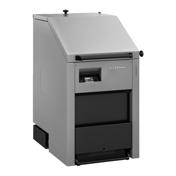
Page 8: Appliance Description
Appliance description The Vitoligno 250-S is suitable for the combustion of Note logs with a moisture content of 15 to 20 %, as well as If the moisture content is greater than 20 %, this can... -
Page 9: Your System Has Been Preset
Introductory information Commissioning Commissioning and matching up of the control unit to As the user, you may be obliged to notify your local local conditions and the structural characteristics of the flue gas inspector of the installation of new combustion building must be carried out by your heating contractor. - Page 10 Introductory information Energy saving tips (cont.) ■ Correct ventilation/airing: Open windows wide for a short time. During this time, close thermostatic valves ■ Do not overheat the rooms; aim for a room tempera- ture of 20 °C. Every degree of room temperature reduction saves up to 6 % on your heating bills.
-
Page 11: Programming Unit
About the controls Programming unit Buffer drawing Boiler Buffer Heating Select with Fig. 3 Display of operating phase Confirms your selection or saves your setting. Dialogue line Calls up the help text relevant to the selected Takes you to the previous step in the menu or can- menu point. - Page 12 About the controls Extended menu Menu Boiler Heating Information Select with Fig. 5 In the extended menu, you can call up and adjust the Call up the extended menu as follows: settings of the control unit's range of less frequently ■...
-
Page 13: How To Use The Controls
About the controls How to use the controls Example: Procedure for settings with different dialogue lines Boiler water temp 48°C Heating Additional boiler Information Select with Heating circuit 1 Heating circuit selection Ù Ú Ù Ú Ù Ú Set room temperature Ú... -
Page 14: Load Operation
Start-up/shutdown Boiler operating phases The operating phases are shown on the programming ■ Residual heat utilisation unit display. After heat up, the boiler runs through the ■ Buffer drawing following operating phases in sequence: Heat up ■ ■ Load operation Heat up After charging and igniting the fuel, the boiler starts up. - Page 15 Start-up/shutdown Heat-up preparations (cont.) 4. Check that the heating system has been vented. 8. Ensure that power is supplied to the boiler. 5. Ensure that all shut-off gate valves to the heating Please note flow and return are open. Risk of damage to the pressure-jet oil/gas burner (if installed) when operating the boiler 6.
- Page 16 Start-up/shutdown Heat-up (cont.) Charging with fuel and igniting Important information ■ Charge with fuel according to the heat demand. ■ Fill the hopper completely if the outside temperature is low and the heating water buffer cylinder is cold. In spring and autumn, only charge as much fuel as required for the actual heat demand and buffer vol- ume.
- Page 17 Start-up/shutdown Heat-up (cont.) 05. Close hopper cover 08. Switch the boiler on at the control unit. Press the "START/STOP" button. Note Ensure that the safety latch engages and that the 09. Now swivel the ash chamber door down and leave hopper cover is securely closed.
- Page 18 If the boiler overheats again after a short time or over- heats regularly, notify your heating contractor. Note Modifications to this component are prohibited and will render all warranties void. Replace faulty components only with genuine spare parts from Viessmann.
-
Page 19: High Limit Safety Cut-Out
Start-up/shutdown Steps to take in the event of overheating (cont.) High limit safety cut-out Reset button of the high limit safety cut-out is loca- ted on the front of the boiler. Fig. 12 Triggering the function If the boiler water temperature exceeds 95 °C the high Note limit safety cut-out responds. -
Page 20: Required Settings
Central heating Room temperature Required settings If you require central heating, check the following Have you selected the correct operating program? ■ points: For information on settings, see page 21. ■ Have you selected the heating circuit? ■ Have you selected the required time program? For information on settings, see chapter "Selecting a For information on settings, see page 21. -
Page 21: Room Temperature
Central heating Room temperature (cont.) Setting the reduced room temperature (night setback) To confirm. Heating circuit 1 Set room temp. To select "Heating circuit 1" (HC1), "Heat- Ù Ú Set red. room temp. ing circuit 2" (HC2) or "Heating circuit 3" (HC3). -
Page 22: Setting Time Phases
Central heating Time program (cont.) ■ At the factory, time phase from 06:00 to 22:00 h Please note when setting the switching times: Your is set for all days of the week. During that time, the heating system requires some time to heat the rooms to the required temperature. -
Page 23: Adjusting The Heating Curves
Central heating Time program (cont.) Restoring the time phases to the factory settings Note The steps for restoring factory settings can be found The time phases are only reset to factory settings on page 33. when you reset all settings for the selected heating cir- cuits. -
Page 24: Stopping The Central Heating
Central heating Heating curve (cont.) For "Slope" For technically-minded system users or "Level". Heating curves illustrate the relationship between the ■ To confirm. outside temperature and the flow temperature. Sim- plified: The lower the outside temperature, the higher For the required value. the flow temperature. - Page 25 Central heating Stopping the central heating (cont.) To select "Heating circuit 1" (HC1), "Heat- To confirm. Ù Ú ing circuit 2" (HC2) or "Heating circuit 3" (HC3). For "Standby mode". For "Operating program". To confirm. The display briefly shows "Standby mode". Comfort function "Party mode"...
- Page 26 Central heating Energy saving function "Economy mode" To save energy, you can reduce the room temperature in standard heating mode, for example if you leave the house for a few hours. Selecting "Economy mode" In economy mode, the standard room temperature is For "Heating".
- Page 27 Central heating Energy saving function "Holiday program" (cont.) To confirm. The current "Departure date" Holiday program and the following "Return date" are dis- Departure date: played. Date Tu 25.02.2014 For departure date. Return date: Date We 26.02.2014 To confirm. Change with Fig.
- Page 28 DHW heating DHW temperature Required settings If you require DHW heating, check the following points: Have you selected the correct operating program? ■ ■ Have you selected the required set DHW tempera- For information on settings, see page 28. ture? ■...
-
Page 29: Stopping Dhw Heating
DHW heating Time program (cont.) Setting time phases Press the following keys: To set the end time. For the "Extended menu". To confirm. å For "DHW". 16. To set the beginning and end of further time pha- ses, proceed as described in steps 10 to 15. To confirm. - Page 30 DHW heating Stopping DHW heating (cont.) For "Operating program". To confirm. For "Standby mode". To confirm.
-
Page 31: Setting The Display Contrast
Further adjustments Setting the display contrast Press the following keys: For "Contrast". For the "Extended menu". To confirm. å For "Settings". For the required contrast. To confirm. To confirm. Setting the brightness of the display To improve the readability of the text in the menu, you For "Brightness". -
Page 32: Setting The Time And Date
Further adjustments Assigning names to heating circuits (cont.) The menu shows "Apartment" for heating circuit 1. Apartment Apartment Ù Ú Set room temperature 22 °C Heating program ß Party mode Economy mode Select with Fig. 30 Setting the time and date The time and date are factory-set. -
Page 33: Setting The Boiler Water Temperature
Further adjustments Setting the boiler water temperature In the delivered condition, the boiler water temperature To confirm. is set to 85 °C. The temperature of the boiler water is controlled to the set value. For "Boiler water temp". Press the following keys: To confirm. - Page 34 Further adjustments Restoring factory settings (cont.) The following settings and values of the selected parameter group are reset: Set room temperature ■ Set DHW temperature ■ ■ Time program for central heating ■ Time program for DHW heating ■ Time program for DHW circulation pump ■...
-
Page 35: Calling Up Information
Information call up Calling up information You can call up information in the standard menu as By selecting the sub-menu "Heating", you can call up well as in the extended menu. The difference lies in information on the required heating circuit via " ". -
Page 36: Calling Up Fault Messages
Information call up Calling up information (cont.) Calling up temperatures Information on temperatures can be called up via the To display the required temperature. standard menu and the extended menu. The range of displayed values is wider in the extended menu. We The following temperatures can be called up in the therefore recommend calling up temperatures via the "Buffer"... - Page 37 Information call up Calling up fault messages (cont.) Calling up a fault message Danger 3. Make a note of the cause of the fault and the fault Unresolved faults in the heating system repre- code shown next to it on the right. In this example: sent a risk "Outside sensor 34"...
- Page 38 Prolonged heating system shutdown Prolonged heating system shutdown If you do not intend using your heating system for a Note while, you can switch it off. We recommend you con- No special measures are required for a temporary sys- tact your heating contractor before and after shutting tem shutdown.
- Page 39 Operation with pressure-jet oil/gas burner (if installed) Pressure-jet oil/gas burner operation Danger Please note The pressure-jet oil/gas burner may still be hot The retractable burner carriage is pre-loaded shortly after operation. Risk of injury due to hot with springs. The pressure-jet oil/gas burner components.
-
Page 40: Rooms Are Too Cold
What to do if... Rooms are too cold Cause Remedy Central heating is switched off. Check the room thermostats. If necessary, change the operating program. Control unit incorrectly set. Check the settings and correct if required: The heating circuit must be ON (see page 21) ■... -
Page 41: There Is No Hot Water
What to do if... There is no hot water Cause Remedy Control unit incorrectly set. Check the settings and correct if required: DHW heating must be ON (see page 28) ■ DHW temperature (see page 28) ■ Time (see page 32) ■... -
Page 42: Replacing Fuses
Maintenance Heating system inspection and maintenance Regular maintenance ensures trouble-free, energy effi- cient and environmentally responsible heating. For this, we strongly advise you to arrange an inspection and maintenance contract with your heating contractor. Boiler Increased boiler contamination raises the flue gas tem- perature and thereby increases energy losses. -
Page 43: Maintenance Intervals
Maintenance Information on cleaning (cont.) ■ Carry out the cleaning at the specified intervals, see Note page 44. The cleaning intervals are intended as a guide that can Only clean the boiler with the cleaning equipment be adapted, if required, to the fuel quality and operat- ■... - Page 44 Maintenance Maintenance intervals (cont.) Interval Activity System user Heating con- tractor Before every heat-up Check the ash chamber, clean if necessary. Weekly Clean the ash chamber. After 100 hours run Clean the tubular heat exchanger. Check the fill level of the tubular heat exchanger ash pan, empty the container if required.
- Page 45 Boiler size Turbulators installed as standard Vitoligno 250-S with 40, 50, 60, 75, 100 and 170 kW Vitoligno 250-S with 85 and 120 kW Repeat steps 4 to 6 below until the tubular heat exchanger is clean:...
- Page 46 Maintenance Cleaning the tubular heat exchanger (cont.) Danger 7. Close cleaning cover Risk of injury to eyes due to falling ash. To clean the tubular heat exchanger, extract the Note turbulators to above head height. Ash may Ensure that the safety latch engages and that the fall into your eyes.
-
Page 47: Cleaning The Combustion Chamber
Maintenance Cleaning the sight glass (cont.) 4. Reinstall the sight glass by following the above steps in reverse order. Cleaning the combustion chamber Fig. 37 Combustion chamber maintenance cover 1. Remove combustion chamber maintenance cover with a suitable tool such as a screwdriver. Undo all wing nuts from the maintenance cover underneath it. - Page 48 Stack the split logs with generous gaps in-between. ■ This allows moisture to be dissipated by the air flow. Approved logs For combustion in the Vitoligno 250-S, the following requirements apply for logs such as split or round logs:...
- Page 49 – Diameter Hardwood: 5 to 15 cm ■ Softwood: 5 to 12 cm ■ Length for Vitoligno 250-S with 40, 50, 60 Max. 50 cm and 75 kW Length for Vitoligno 250-S with 85, 100, L100 Max. 100 cm 120 and 170 kW Water content Max.
- Page 50 Appendix Terminology Setback mode (reduced heating mode) Standard room temperature See "Reduced heating mode". For periods when you will be at home during the day, select the standard room temperature. Extension kit for heating circuit with mixer Open flue operation Assembly (accessories) for controlling a heating circuit with mixer The combustion air is drawn from the room where the...
-
Page 51: Final Decommissioning And Disposal Of The Heating System
(Altstoff Recycling Austria AG, licence num- ber 5766). Final decommissioning and disposal of the heating system Viessmann products can be recycled. Components and fluids from your heating systems are not part of ordinary domestic waste. Please contact your heating contractor in connection with the correct disposal of your old system. - Page 52 Keyword index Keyword index Display backlighting........... 31 Activating Drinking water filter..........42, 50 – Comfort function............25 Actual temperature.............50 Economy mode............26 – Selecting..............26 Boiler – Terminating..............26 – Components..............8 Energy saving.............. 9 – Overheating of the boiler.........18 Energy saving function –...
- Page 53 Keyword index Keyword index (cont.) High limit safety cut-out..........19 Holiday program Recharging..............17 – Changing..............27 Reduced heating mode..........50 – Selecting..............26 Reduced room temperature........50 – Setting..............26 Reduced room temperature (night temperature)..21 – Terminating..............27 Reset................33 Residual oxygen – Adjusting the set value..........33 Information Restarting..............14 –...
- Page 54 Keyword index Keyword index (cont.) Time program – Central heating............21 Weather-compensated mode........50 – DHW heating............28 Wintertime/summertime changeover......9 Tips on energy saving..........9 Wintertime changeover..........9 Troubleshooting............40 Wood fuel Tubular heat exchanger – Limits...............48 – Cleaning..............45 – Cleaning ash pan............ 46 Use................7...
-
Page 56: Your Contact
Your contact Contact your local contractor if you have any questions regarding the maintenance and repair of your system. You may, for example, find local contractors on the internet under www.viessmann.com. Viessmann Werke GmbH&Co KG Viessmann Limited D-35107 Allendorf Hortonwood 30, Telford...
Need help?
Do you have a question about the VITOLIGNO 250-S and is the answer not in the manual?
Questions and answers