Table of Contents
Advertisement
Quick Links
Model 5304
Intercom Station
User Guide
Issue Preliminary 1. December 2021
This User Guide is applicable for serial numbers
M5304-00151 and later with Application Firmware 1.02 and later
Copyright © 2021 by Studio Technologies, Inc., all rights reserved
studio-tech.com
50715-1221, Issue Preliminary 1
Advertisement
Table of Contents

Subscribe to Our Youtube Channel
Related Manuals for Studio Technologies 5304


Summary of Contents for Studio Technologies 5304
- Page 1 Intercom Station User Guide Issue Preliminary 1. December 2021 This User Guide is applicable for serial numbers M5304-00151 and later with Application Firmware 1.02 and later Copyright © 2021 by Studio Technologies, Inc., all rights reserved studio-tech.com 50715-1221, Issue Preliminary 1...
- Page 2 This page intentionally left blank.
-
Page 3: Table Of Contents
Table of Contents Revision History ..........................4 Introduction............................5 Getting Started ..........................8 Dante Configuration .......................... 11 Model 5304 Configuration ......................... 12 Operation............................17 Technical Notes ..........................17 Specifications ............................ 20 Appendix A–STcontroller Default Configuration Values ..............22 Appendix B– Graphical Description of the Installation Kit for Panel-Cutout or Surface-Mounting Use (Order Code RMBK-10) ...................... -
Page 4: Revision History
Model 5304 INTERCOM STATION Revision History Issue Preliminary 1, December 2021: • Initial preliminary release. Issue Preliminary 1, December 2021 Model 5304 User Guide Page 4 Studio Technologies, Inc. -
Page 5: Introduction
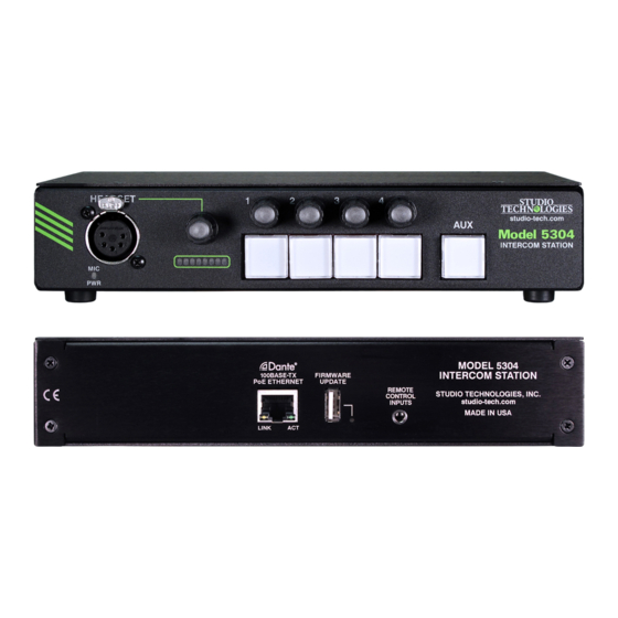
Optional mounting kits allow network (LAN). This connection provides both power one or two Model 5304 units to be mounted in one and bidirectional digital audio. Two LEDs provide an space (1U) of a standard 19-inch rack enclosure. - Page 6 It can serve as an audio level meter, providing Audio signals arrive in the Model 5304 by way of a real-time indication of the microphone signal as it is four Dante receiver (input) channels. These audio sent to one or more of the active “talk”...
- Page 7 RJ45 jack. Two LEDs display the Configuration Flexibility status of the network connection. A highlight of the Model 5304 is its ability to be easily The Model 5304’s operating power is provided configured to meet the needs of specific users and by way of the Ethernet interface using the 802.3af...
-
Page 8: Getting Started
The Model 5304’s location will depend on where the kit, purchased as an option, allows one unit to be user needs access to it. The Model 5304 is shipped as mounted in a panel cutout or on a wall surface. Three a self-contained “throw down”... - Page 9 Installation kit RMBK-12 is used to allow two Model Once the two standard-length brackets have been 5304 units to be mounted in one space (1U) of a installed the Model 5304 will be ready to be mounted standard 19-inch equipment rack. The kit can also be onto a flat surface.
- Page 10 (when machine screws to attach one of the medium-length viewed from the front) of one of the Model 5304 units. brackets onto the left side (when viewed from the The screws will mate with the threaded fasteners that front) of the enclosure.
-
Page 11: Dante Configuration
A balanced dynamic microphone should, in most cases, also function correctly if the signal – (low) is For audio to pass to and from the Model 5304 requires connected to Model 5304’s mic in –/shield connection. that several Dante-related parameters be config- No support is provided for microphones that require ured. -
Page 12: Model 5304 Configuration
Model 5304 Clocking Source The Model 5304 has a default Dante device name While technically the Model 5304 can serve as a Lead- of ST-M5304- followed by a unique suffix. The suf- fix identifies the specific Model 5304 that is being er clock for a Dante network (as can all Dante-enabled configured. - Page 13 When a voice signal at a normal level is present on the connected microphone and at least one of the talk one or more Model 5304 units to be configured will appear in the device list. Use the Identify command...
- Page 14 The overall is present is the area where the Model 5304 located. level control will impact the sidetone level. System – Input Signal Present Display Sidetone –...
- Page 15 This configuration choice allows an audio console mode in homage to how radio station selection buttons “solo” function to be available to Model 5304 users. in an automobile radio can be configured. If Multiple When selected for Off the solo function is disabled.
- Page 16 Upon Model 5304 power up the button will be in its inactive state. Right: In this mode the input audio will be sent only to the right headphone output channel.
-
Page 17: Operation
Ultimo integrated circuits to implement Dante. The voice audio.) Model 5304 uses an UltimoX4 “chip” and, as such, a direct one-to-one interconnection between it and Off: When this mode is selected and a call signal is... - Page 18 (PoE) present to the RJ45 jack. It’s possible that updated versions of the application 4. After a few seconds the Model 5304 will run a “boot firmware (embedded software) that is utilized by loader” program that will automatically load the the Model 5304’s microcontroller (MCU) integrated...
- Page 19 This application is available, free of charge, from the Audinate website (audinate.com). The latest Model 5304 firmware file, with a name in the form of M5304vXrX.dnt, is always available on the Studio Technologies’ website as well as being part of Audi- nate’s product library database.
-
Page 20: Specifications
Software Updating: USB flash drive used for Compressor: updating application firmware; Dante Updater Threshold: 1.5 dB above nominal level application for updating Dante interface firmware (–18.5 dBFS) Slope: 2:1 Issue Preliminary 1, December 2021 Model 5304 User Guide Page 20 Studio Technologies, Inc. - Page 21 RMBK-13 allows one unit to be mounted in the center of one space (1U) of a standard 19-inch rack Specifications and information contained in this User Guide subject to change without notice. Model 5304 User Guide Issue Preliminary 1, December 2021 Studio Technologies, Inc. Page 21...
-
Page 22: Appendix A-Stcontroller Default Configuration Values
Channel Specific Menu Page (all parameters identical for Channels 1-4): Button Mode: Push to Talk/Tap to Latch Button Function: Talk Headset Routing: Left and Right Call Indication: Flash Issue Preliminary 1, December 2021 Model 5304 User Guide Page 22 Studio Technologies, Inc. -
Page 23: Appendix B- Graphical Description Of The Installation Kit For Panel-Cutout Or Surface-Mounting Use (Order Code Rmbk-10)
Appendix B–Graphical Description of the Installation Kit for Panel Cutout or Surface-Mounting Use (Order Code: RMBK-10) This installation kit is used for mounting one Model 5304 unit into a panel cutout or flat surface. Model 5304 User Guide Issue Preliminary 1, December 2021 Studio Technologies, Inc. -
Page 24: Appendix C-Graphical Description Of Left- Or Right-Side Rack-Mount Installation Kit For One "1/2- Rack" Unit (Order Code Rmbk-11)
Installation Kit for One “1/2-Rack” Unit (Order Code: RMBK-11) This installation kit is used for mounting one Model 5304 unit into one space (1U) of a 19-inch equipment rack. Unit will be located on the left- or right-side of the 1U opening. -
Page 25: Appendix D-Graphical Description Of Rack-Mount Installation Kit For Two "1/2- Rack" Units (Order Code Rmbk-12)
Two “1/2-Rack” Units (Order Code: RMBK-12) This installation kit can be used to mount two Model 5304 units or one Model 5304 unit and another product that is compatible with the RMBK-12 (such as the Studio Technologies’ Model 5421 Dante Intercom Audio Engine) into one space (1U) of a 19-inch equipment rack. -
Page 26: Appendix E-Graphical Description Of Center Rack-Mount Installation Kit For One "1/2- Rack" Unit (Order Code Rmbk-13)
One “1/2-Rack” Unit (Order Code: RMBK-13) This installation kit is used for mounting one Model 5304 unit into one space (1U) of a 19-inch equipment rack. Unit will be located in the center of the 1U opening. Issue Preliminary 1, December 2021...
Need help?
Do you have a question about the 5304 and is the answer not in the manual?
Questions and answers