Advertisement
Quick Links
Advertisement

Related Manuals for Studio Technologies 370A


Summary of Contents for Studio Technologies 370A
- Page 1 Model 370A Intercom Beltpack User Guide Issue 2, August 2019 This User Guide is applicable for serial numbers M370A-02501 and later with application firmware 1.2 and later Copyright © 2019 by Studio Technologies, Inc., all rights reserved www.studio-tech.com 50636-0819, Issue 2...
- Page 2 This page intentionally left blank.
-
Page 3: Table Of Contents
Table of Contents Revision History ............4 Introduction ..............5 Getting Started .............. 8 Operation ..............13 Technical Notes ............. 17 Specifications ..............22 Appendix A ..............23 Model 370A User Guide Issue 2, August 2019 Studio Technologies, Inc. Page 3... -
Page 4: Revision History
Issue 2, August 2019: 1. Documents revision to STcontroller (version 2.02.00 and later) which separates microphone power and microphone gain configuration. Issue 1, June 2018: 1. Initial release. Issue 2, August 2019 Model 370A User Guide Page 4 Studio Technologies, Inc. -
Page 5: Introduction
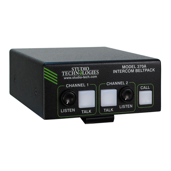
AV installations, and post-production facilities. Figure 1. Model 370A Intercom Beltpack top and bottom views Model 370A User Guide Issue 2, August 2019 Studio Technologies, Inc. Page 5... - Page 6 Controller’s Identify command takes on a driver circuitry. High signal levels can be unique role with the Model 370A. Not only provided to a variety of headsets, head- will it cause the talk and call button LEDs phones, and earpieces.
- Page 7 MODEL 370A INTERCOM BELTPACK Configuration Flexibility Ethernet Data and PoE A highlight of the Model 370A is its ability The Model 370A connects to an Ethernet to be easily configured to meet the needs data network using a standard 100 Mb/s of specific users and applications.
-
Page 8: Getting Started
Refer to Figure 2 for connection details. on the bottom of the Model 370A’s enclo- The microphone input connections are sure. An Ethernet data connection with compatible with most unbalanced dynamic... - Page 9 Model 370A’s headset connector as dam- receiver (Rx) channels. This achieves rout- age to the Model 370A’s output circuitry ing the Model 370A’s two talk output audio could result. channels to the device (or devices) that Monaural (single-earpiece or “single will be “listening”...
- Page 10 Electret local area network (LAN) and subnet as Power check box. If the associated headset the Model 370A unit or units that are to be has a dynamic (non-powered) microphone configured. do not enable the Electret Power check box.
- Page 11 The three options provide flexibility When a dynamic microphone is connected in how the audio sources are presented to the Model 370A the 42 dB gain setting to the user. When using a stereo (“double may be correct for many applications. Set- muff”) headset it’s common for the audio...
- Page 12 Pressing and holding the talk Medium, Medium High, and High. button will enable audio to be sent out The Model 370A includes a sidetone its associated Dante transmitter channel. function that allows microphone audio When the button is released audio will...
-
Page 13: Operation
Model 370A’s two audio output chan- another Dante device. The SYNC LED nels (Dante transmitter channels) and two will light red when the Model 370A is not audio input channels (Dante receiver chan- synchronized with a Dante network. It will... - Page 14 The button will not be lit when the Two rotary potentiometers (“pots”), locat- function is not active. ed on the Model 370A’s top panel, allow individual adjustment of the level of the Latching two audio input signals as they are sent to If a button has been configured for the...
- Page 15 MODEL 370A INTERCOM BELTPACK the talk function. When released the talk 370A unit. Also, the two headphone level function will turn off. Momentarily pressing controls on the top panel of the unit do not (“tapping”) the button will cause the func- impact the sidetone level.
- Page 16 Whenever a Model 370A audio input chan- be used to help locate a specific Model nel receives a call signal (20 kHz audio 370A. When Identify is selected it will send tone) the orange LED on its companion a command to a single Model 370A unit.
-
Page 17: Technical Notes
INTERCOM BELTPACK state. This allows one or both talk chan- world as Automatic Private IP Addressing nels on a specific Model 370A that have (APIPA). It is also sometimes referred to been enabled to be remotely disabled. as auto-IP . Link-local will randomly assign The reason for this function is simple. - Page 18 Ethernet switch connecting a personal net cable. Upon application of PoE power computer to the Model 370A. Then by the Model 370A will go through its normal using the appropriate ARP command the power-up sequences followed by a display required “clues” can be obtained.
- Page 19 file into the MCU’s non-volatile flash memory level controls and buttons and then lift by way of a USB interface. The Model 370A it off. implements a USB host function that directly supports connection of a USB flash drive.
- Page 20 MODEL 370A INTERCOM BELTPACK 6. At this time the Model 370A is operat- be used to determine the version of the ing under the newly-saved application firmware (embedded software) that resides firmware and the USB flash drive can in the Ultimo “chip.” The STcontroller be removed.
- Page 21 • The DIP switch assembly on the Model 370 Intercom Beltpack units, the belt clip 370 is not present on the Model 370A. on the Model 370A will never have to be As such the belt clip no longer needs rotated as part of the configuration pro- to be rotated and its mounting arrange- cess.
-
Page 22: Specifications
Compressor: Mounting: intended for portable applications; con- tains integral belt clip; optional MBK-01 Mounting Threshold: 1 dB above nominal level (–19 dBFS) Bracket Kit allows Model 370A to be permanently Slope: 2:1 mounted Status LED: compressor active Weight: 0.6 pounds (0.3 kg) -
Page 23: Appendix A
MODEL 370A INTERCOM BELTPACK Appendix A STcontroller default Model 370A configuration values: Microphone Input – Electret Power: Off Microphone Input – Gain: 42 dB Headphone Output – Channel 1 Input Routes to: Left Headphone Output – Channel 2 Input Routes to: Right Sidetone –...
Need help?
Do you have a question about the 370A and is the answer not in the manual?
Questions and answers