Table of Contents
Advertisement
Quick Links
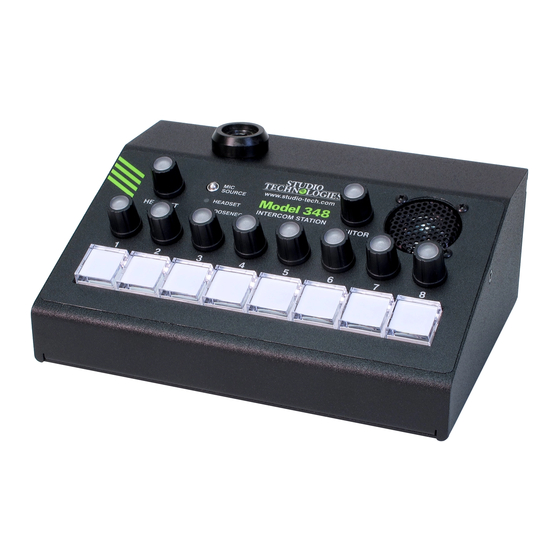
Model 348
Intercom Station
User Guide
Issue 8, July 2022
This User Guide is applicable for serial numbers
M348-00251 and later with main firmware version 2.05 and later
and STcontroller application version 3.08.00 and later.
Also applicable to units with serial numbers
M348-00151 to 00250; see Appendix C for details.
Copyright © 2022 by Studio Technologies, Inc., all rights reserved
studio-tech.com
50291-0722, Issue 8
Advertisement
Table of Contents

Subscribe to Our Youtube Channel
Related Manuals for Studio Technologies 348


Summary of Contents for Studio Technologies 348
- Page 1 M348-00251 and later with main firmware version 2.05 and later and STcontroller application version 3.08.00 and later. Also applicable to units with serial numbers M348-00151 to 00250; see Appendix C for details. Copyright © 2022 by Studio Technologies, Inc., all rights reserved studio-tech.com 50291-0722, Issue 8...
- Page 2 This page intentionally left blank.
-
Page 3: Table Of Contents
Technical Notes ..................26 Specifications ..................30 Appendix A–STcontroller Default Configuration Values ......32 Appendix B–3-Pin Header Connector Details ......... 33 Appendix C–Differences between Model 348 Units as Noted by Serial Number Range ................34 Model 348 User Guide Issue 8, July 2022 Studio Technologies, Inc. -
Page 4: Revision History
Clarifies the Microphone Input – Source function in STcontroller. Issue 2, August 2020: • Corrects errors in Issue 1. Issue 1, January 2020: • Initial release of complete document. Issue 8, July 2022 Model 348 User Guide Page 4 Studio Technologies, Inc. -
Page 5: Introduction
A The range of resources makes it simple to use the low-noise microphone preamplifier and associated Model 348 locally, or as part of a REMI or “At-Home” voltage-controlled-amplifier (VCA) dynamics controller geographically diverse implementation. In addition... - Page 6 The user can monitor the Ethernet Data and PoE Dante audio inputs by means of a headset, a built-in The Model 348 connects to one or two local speaker, or two Dante transmitter (output) channels. area networks (LANs) by way of two twisted-pair Two additional rotary encoders are used to control Ethernet interfaces.
-
Page 7: Getting Started
12 volts DC to power the Model supports sampling rates of 48 kHz. A Dante receiv- 348. If this is the case then a power supply would need er (input) channel can be used as an alternate talk to be provided separately. - Page 8 An external source of 12 volts DC can be connected voltage DC-powered) microphones. A balanced to the Model 348 by way of the 4-pin male XLR con- dynamic microphone should, in most cases, also nector which is located on the back panel. While the function correctly if its signal –...
- Page 9 DC source for the STcontroller software application, as discussed operation. The Model 348 is able to provide this power in later sections, can be used to create the desired and requires only that the appropriate setting in the monaural output.
-
Page 10: Dante Configuration
Model 348 INTERCOM STATION The 3-conductor 1/4-inch jack associated with the 348, is 16 so there’s a minimal chance of a flow limita- Model 348’s gooseneck bushing has a tip connection tion. These flows can either be unicast, multicast, or a that is used for both microphone audio as well as for combination of the two. -
Page 11: Model 348 Configuration
Enabled. By default, AES67 mode is set for Disabled. to the LAN associated with the Dante devices. If both of the Model 348’s RJ45 jacks are routed to ports on Model 348 Clocking Source the same LAN this will typically “crash” the network! - Page 12 Each time a change is made the eight but- Microphone Input – Headset Mic Gain tons on the Model 348’s front panel will flash orange in Choices are 26 dB, 32 dB, 38 dB, 44 dB, and 50 dB...
- Page 13 Speaker – Dim switch on the Model 348’s front panel will not allow Choices are 0 dB, 6 dB, 12 dB, and 18 dB the Aux In channel to be selected.
- Page 14 This function allows the muted/unmuted state of the Whenever a talk or IFB function is active the Model headset’s headphone outputs, the Dante monitor 348 will invoke a dim (attenuation) function. This is outputs (when configured for post-fader), and the designed to help achieve maximum intelligibility and...
- Page 15 Choices are Off, Talkback 1 Button, Talkback 2 Button, Talkback 3 Button, Talkback 4 Button, The Model 348 is capable of generating an audible Talkback 5 Button, Talkback 6 Button, Talkback 7 alerting signal when a call signal is detected on a Button, and Talkback 8 Button channel that is assigned to the Monitor A audio bus.
- Page 16 INTERCOM STATION green LED will be lit whenever the associated function IFB: In this mode, the Model 348 channel will be used is active. Upon Model 348 power up the button will be to create a broadcast-type IFB (interrupted foldback in its inactive state and its LEDs will not be lit.
- Page 17 A visual and audible indication can be provided when- only the right headphone output channel. ever a call signal has been detected on a Model 348 input channel. The visual indication is provided by the Left and Right: In this mode, the input audio will LED indicators associated with each rotary encoder.
-
Page 18: Operation
Model 348 INTERCOM STATION Operation Initial Operation The Model 348 will start to function as soon as a At this point all connections and configuration Power-over-Ethernet (PoE) or a 12 volts DC power steps should have been completed and everything source is connected. - Page 19 When Identify is selected it will send a command switches, the mic source status display, and the ten to a specific Model 348 unit. On that unit the red LEDs rotary encoders. Using the STcontroller software ap- associated with the eight pushbutton switches will plication the intensity of these LEDs, as a group, can “flash”...
- Page 20 (“tapped”). The pushbutton’s green LEDs will mute. In both cases the mute state that was automati- be lit whenever the function is active. Upon Model 348 cally enabled can be overridden by pressing the knob power up the button’s associated function will be in on the applicable rotary encoder.
- Page 21 Note that there is no means green whenever the function is active. The associ- provided within the Model 348 to adjust the level of the ated Dante transmitter (output) channel will not be IFB program input sources. This should not be con-...
- Page 22 One is to press and hold a rotary encoder’s On the front panel of the Model 348 there are knob. One or more of the eight pushbutton switches ten rotary encoders. Eight of the rotary encoders are will light orange.
- Page 23 4-pin 3.5 mm TRRS plug can be connected with one has been set to steps 5-8, etc. Step 1 is considered of the headset connectors on the Model 348’s back to be mute and causes pushbutton switch 1 to flash panel.
- Page 24 Monitor Output a reference level as to how much microphone audio The Model 348’s monitor section consists of a rotary signal, headset, gooseneck, or Aux In is being sent encoder, two Dante audio output channels, and an out the Dante transmitter (output) channels.
- Page 25 Model 348’s monitor when the microphone source is selected for Headset. rotary encoder. If configured for pre-fader the level of...
-
Page 26: Technical Notes
For descriptive purposes, this dows OS the arp –a command can be used to display text will refer to one Model 348 as the Leader and a a list of LAN information that includes MAC addresses second Model 348 as the Follower. The Leader will be and corresponding IP addresses. - Page 27 Refer to the Audinate website (audinate.com) thread pitch hardware that secures the blank plate for details on how to optimize a network for Dante to the Model 348’s back panel is also intended to be applications. used to secure the selected connector.
- Page 28 LEDs Model 348, the name of the zip file itself will include associated with them. The FPGA firmware is used by the file’s version number. For example, a file named the field-programmable-gate-array integrated circuit M348v2r05MCU.zip would indicate that version 2.05...
- Page 29 Broadway firmware. The Dante Controller software 5. After a few seconds the Model 348 will run a “boot application also includes an automated method of loader” program that will automatically load and updating Broadway firmware.
-
Page 30: Specifications
1 phones right; ring 2 common; sleeve mic configurable Type: unbalanced Impedance: 1 k ohms, nominal, microphone power off; 690 ohms, nominal, microphone power on Gain: 26, 32, 38, 44, 50 dB, selectable Issue 8, July 2022 Model 348 User Guide Page 30 Studio Technologies, Inc. - Page 31 Altitude: not characterized Duration: 250 milliseconds Spare Connector Location: 1 Level: –28 dBFS Allows a Studio Technologies’ cable assembly or Call Function: option module to be installed. Also compatible with Receive Frequency: 20 kHz, ±800 Hz, within audio Neutrik NC*D-L-1 connectors (*=3F, 3M, 5M, 6F, channel 6FS, etc.).
-
Page 32: Appendix A-Stcontroller Default Configuration Values
Model 348 INTERCOM STATION Appendix A–STcontroller Default Model 348 Configuration Values General Menu Page: Microphone Input – Source: Headset Microphone Input – Headset Mic Power: Off Microphone Input – Headset Mic Gain: 38 dB Microphone Input – Gooseneck Mic Gain: 24 dB Microphone Input –... -
Page 33: Appendix B-3-Pin Header Connector Details
Model 348 INTERCOM STATION Appendix B–3-Pin Header Connector Details The following list provides details on the 3-pin header connectors located on the Model 348’s printed circuit boards. Shown are both reference numbers and associated functions. Header on Main (“Broadway”) Board: P7: Remote In 1, Remote In 2 Pin 1: Common (–) -
Page 34: Appendix C-Differences Between Model 348 Units As Noted By Serial Number Range
There are several differences between Model 348 units with serial numbers M348-00151 to 00250 and Model 348 units with serial numbers M348-00251 and later. In most cases, the differences will not impact using a unit in typical applications. However, it may be important to note the differences for specialized or unique applications.
Need help?
Do you have a question about the 348 and is the answer not in the manual?
Questions and answers