Table of Contents
Advertisement
Quick Links
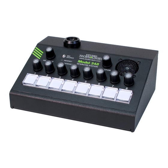
Model 348 Intercom Station
User Guide
Issue 5, May 2021
This User Guide is applicable for serial numbers
M348-00251 and later with Main Firmware version 2.01 and later
and STcontroller application version 3.03.00 and later.
Copyright © 2021 by Studio Technologies, Inc., all rights reserved
studio-tech.com
50291-0521 Issue 5
Advertisement
Table of Contents

Subscribe to Our Youtube Channel
Related Manuals for Studio Technologies 348


Summary of Contents for Studio Technologies 348
- Page 1 Issue 5, May 2021 This User Guide is applicable for serial numbers M348-00251 and later with Main Firmware version 2.01 and later and STcontroller application version 3.03.00 and later. Copyright © 2021 by Studio Technologies, Inc., all rights reserved studio-tech.com 50291-0521 Issue 5...
- Page 2 This page intentionally left blank.
-
Page 3: Table Of Contents
Table of Contents Revision History ..............4 Introduction ................5 Getting Started ................. 8 Dante Configuration ..............11 Model 348 Configuration ............13 Operation ................. 21 Technical Notes ............... 31 Specifications ................36 Appendix A–STcontroller Default Configuration Values ... 38 Appendix B–3-Pin Header Connector Details ...... -
Page 4: Revision History
Clarifies the Microphone Input – Source function in STcontroller. Issue 2, August 2020: • Corrects errors in Issue 1. Issue 1, January 2020: • Initial release of complete document. Issue 5, May 2021 Model 348 User Guide Page 4 Studio Technologies, Inc. -
Page 5: Introduction
Model a dynamic or electret (DC powered) micro- 348 locally, or as part of a REMI or “At-Home” phone. The unit provides both a 5-pin female geographically diverse implementation. In XLR and a 3.5 mm TRRS connector allow-... - Page 6 This was specif- specialized applications. They can be inde- ically included to allow two Model 348 units to pendently configured for talk (intercom), IFB “work” together to support more than eight talk (talent cue), call signal (20 kHz tone), and channels.
- Page 7 MODEL 348 INTERCOM STATION Ethernet Data and PoE Audio Quality The Model 348 connects to one or two local The Model 348’s audio performance is com- area networks (LANs) by way of two twisted- pletely “pro.” A low-noise, wide dynamic-range pair Ethernet interfaces.
-
Page 8: Getting Started
12 volts DC to power the Model circuitry allowing external switches to activate 348. If this is the case then a power supply two of the button functions. Refer to the Tech- would need to be provided separately. - Page 9 An external source of 12 volts DC can be trically wired in parallel. As such, only one type connected to the Model 348 by way of the of headset should be connected at one time. 4-pin male XLR connector which is located on Headset A the back panel.
- Page 10 3.5 mm TRS jack for the headphones. In this scenario the microphone would, in most cases, Figure 2. Headset A connection pinout chart be a dynamic type as the Model 348 provides for microphones that require P12 or P48 phan- only low-voltage DC electret power. Phantom- tom power.
-
Page 11: Dante Configuration
The number of transmitter flows associated with a Broadway integrated circuit and, The Model 348’s gooseneck bushing includes as such, the Model 348, is 16 so there’s a a hex head socket set screw with a thread minimal chance of a flow limitation. These pitch of 4-40 UNC. - Page 12 If Switched is selected (the factory default) ing. The second set of eight Dante receiver then the Model 348 will be able to establish (input) channels are associated with the IFB one connection with an Ethernet network. It (talent cue) functions.
-
Page 13: Model 348 Configuration
IP address. of the Windows and macOS operating systems. If knowledge of a Model 348’s IP address has If required, download and install STcontroller been misplaced there is no reset button or other onto a designated personal computer. - Page 14 36 dB. set A connector. When the gooseneck microphone is se- Note that the Model 348 cannot supply P12 or lected as the Model 348’s microphone audio P48 phantom power that may be required by source the gain of the microphone preampli- balanced condenser (capacitor) microphones.
- Page 15 To prevent this from happening se- Model 348’s front panel will not allow the Aux lecting a dim configuration of 6, 12, or 18 dB In channel to be selected.
- Page 16 Pre-Fader: In this mode the audio level and on/off status of Dante monitor output channels Choices are Off, Monitor A, and Monitor B. will not be impacted by the Model 348’s moni- The Model 348 includes an internal loudspeak- tor output rotary encoder. To clarify, neither er of which an audio source can be selected level adjustment or on/off control will occur.
- Page 17 It will always appear in the list of optimal will depend on the amount of ambient available channels as shown in Dante Con- light present where the Model 348 is located. troller. But no audio will be present on the System – Headset and Monitor Outputs...
- Page 18 Input 1 is enabled will follow the configura- Upon Model 348 power up the button will be tion selected from among nine choices. When in its inactive state and its LEDs will not be lit.
- Page 19 Upon the function is not active audio from the corre- Model 348 power up the button will be in its sponding Dante receiver (input) IFB program inactive state and its LEDs will not be lit.
- Page 20 Model 348 channel can be monitored with each rotary encoder. The audible indica- using the headset’s headphone outputs. The tion is provided by way of the Model 348’s destination channel(s) can be configured as internal loudspeaker and, if configured appro- desired.
-
Page 21: Operation
12 volts DC may have been connected to IFB operation. provide power for the Model 348. A stereo or monaural headset will typically be interfaced Initial Operation using either the Headset A or Headset B con- The Model 348 will start to function as soon nector. - Page 22 348 is not synchronized with a Dante network. An LED indicator, orange in color, is located It will light solid green when the Model 348 is on the back panel adjacent to the Headset A synchronized with a Dante network and an connector.
- Page 23 Conversely, Dante Aux In receiver (input) channel will be if the COMP LED almost never lights when serving as the talk audio source. A Model 348 normal talking is taking place it’s possible that power-down/power-up cycle will return the changing the gain to a higher value would be microphone source to its last selection.
- Page 24 MODEL 348 INTERCOM STATION choice for the headset and gooseneck micro- the function is active. Upon Model 348 power phone preamplifier gain and Aux In level up the button’s associated function will be in trim should be reviewed and revised as its inactive state.
- Page 25 18 kHz and are active will have a 20 kHz sine the program audio sources. Note that there wave tone at a level of –20 dBFS added to is no means provided within the Model 348 their associated Dante transmitter (output) to adjust the level of the IFB program input channels.
- Page 26 18 kHz Tone the channel’s operation is very simple. When the pushbutton is pressed or the On the front panel of the Model 348 there are function is active an 18 kHz sine wave tone ten rotary encoders. Eight of the rotary encod- at –20 dBFS is connected to the associated...
- Page 27 (1 and 1/3 full rotations) are required to move each rotary encoder’s location when a Model between the minimum and maximum levels. 348 is being used in an environment where Each pushbutton switch will light orange in the ambient light is very low or nonexistent. A response to a rotary encoder being within a rotary encoder knob that’s lit dark blue could...
- Page 28 Model 348’s back panel. The connectors are labeled Headset A and Headset B. Sidetone A sidetone function is available for assisting...
- Page 29 Monitor Output headset, gooseneck, or Aux In is being sent out the Dante transmitter (output) channels. The Model 348’s monitor section consists of a rotary encoder, two Dante audio output Headset Headphone Output Dim channels, and an internal loudspeaker. These...
- Page 30 Call Indication up by selected microphone. The Model 348 can be configured to respond to Loudspeaker Output call signals that are present in any of the eight The Model 348 contains a small loudspeaker Dante receiver (input) channels.
-
Page 31: Technical Notes
Dante monitor output purposes, this text will refer to one Model 348 channels and the internal loudspeaker. Using as the Leader and a second Model 348 as the STcontroller there are individual configuration Follower. The Leader will be used to provide... - Page 32 Once a cap is removed a custom label could ler software application. In the unfortunate be inserted between it and the translucent event that a specific Model 348’s IP address is lens. Then the cap could be “snapped” back “lost,” the Address Resolution Protocol (ARP) onto the body of the switch.
- Page 33 0.1-inch center headers allow “no solder” so- pitch hardware that secures the blank plate to lutions which makes customizing a Model 348 the Model 348’s back panel is also intended to unit a relatively simple process. The headers be used to secure the selected connector.
- Page 34 M348.bin. For the secondary firm- ware the file name must be M348sec.bin. And To observe the firmware version numbers, begin by connecting the Model 348 unit to a for the FPGA firmware the file name must be network. Connect an external source of 12 BWY.bit.
- Page 35 Note that upon power being applied to the 348’s back panel, labeled Firmware Up- Model 348 if the USB flash drive doesn’t have date. Directly below the USB connector is the correct file(s) in its root folder no harm will a small hole that provides visual access to occur.
-
Page 36: Specifications
22 Hz to 22 kHz bandwidth, 38 dB of gain Frequency Response: 150 Hz to 20 kHz, ±3 dB Dynamic Range: >93 dB, A-weighted, 26 dB gain Dim (Attenuation): 0, 6, 12, 18 dB, configurable Issue 5, May 2021 Model 348 User Guide Page 36 Studio Technologies, Inc. - Page 37 Altitude: not characterized Duration: 250 milliseconds Spare Connector Location: 1 Level: –28 dBFS Allows a Studio Technologies’ cable assembly or op- Call Function: tion module to be installed. Also compatible with Neutrik Receive Frequency: 20 kHz, ±800 Hz, within audio NC*D-L-1 connectors (*=3F, 3M, 5M, 6F, 6FS, etc.).
-
Page 38: Appendix A-Stcontroller Default Configuration Values
MODEL 348 INTERCOM STATION Appendix A–STcontroller Default Model 348 Configuration Values General Menu Page: Microphone Input – Source: Headset Microphone Input – Headset Mic Power: Off Microphone Input – Headset Mic Gain: 38 dB Microphone Input – Gooseneck Mic Gain: 24 dB Microphone Input –... -
Page 39: Appendix B-3-Pin Header Connector Details
MODEL 348 INTERCOM STATION Appendix B–3-Pin Header Connector Details The following list provides details on the 3-pin header connectors located on the Model 348’s printed circuit boards. Shown are both reference numbers and associated functions. Header on Main (“Broadway”) Board: P7: Remote In 1, Remote In 2 Pin 1: Common (–)
Need help?
Do you have a question about the 348 and is the answer not in the manual?
Questions and answers