Table of Contents

Subscribe to Our Youtube Channel
Related Manuals for Studio Technologies M45 Interface


Summary of Contents for Studio Technologies M45 Interface
- Page 1 User Guide Issue Preliminary 2, March 2009 This User Guide is applicable for serial numbers M45-00151 and later Copyright © 2009 by Studio Technologies, Inc., all rights reserved www.studio-tech.com 50216-0309, Issue Preliminary 2...
- Page 2 This page intentionally left blank.
-
Page 3: Table Of Contents
Table of Contents Introduction ..............5 Installation ..............10 Configuration ..............16 Operation ..............19 Technical Notes ............. 24 Specifications ..............27 Appendix A—Interfacing with RTS® Matrix Intercom Systems ..........28 Appendix B—Interfacing with Riedel® Artist™ Matrix Intercom Systems ..........29 Appendix C—Interfacing with Clear-Com®... - Page 4 This page intentionally left blank. Issue Preliminary 2, March 2009 Model 45 User Guide Page 4 Studio Technologies, Inc.
-
Page 5: Introduction
Introduction The connected party-line intercom circuit can also provide the Model 45’s operat- The Model 45 is designed to interface ing power. For maximum flexibility the unit 2-wire full-duplex party-line (PL) intercom is capable of supplying 30 volt DC power circuits with 4-wire audio circuits associ- and AC terminations, thus creating a ated with matrix intercom systems. - Page 6 2-Wire Party-Line Interface mode the 30 volt, 300 milliampere maxi- mum output can power devices such as The Model 45’s two-channel 2-wire party- user stations and belt packs. In many line interface is optimized for direct connec- applications this will eliminate the need tion with a dual-channel party-line intercom for an external intercom power supply.
- Page 7 of its 2-wire-to-4-wire hybrid circuits. Each highlight that while the nulling process is of the two independent circuits provides automatic, it only takes place upon user low noise and distortion, good frequency request. The parameters obtained during response, and high return-loss (“nulling”), the nulling process are stored in nonvola- even when presented with a wide range tile memory;...
- Page 8 of only 2 dB is required. The RTS ADAM™ to be essentially identical to that of the series of matrix intercom systems has a unpowered (“dry”) channel. This unique nominal level of +8 dBu. This level also situation allows the automatic nulling applies to their RVON-I/O VoIP products.
- Page 9 Design Philosophy audio quality, advanced users might need to disable it. This would allow full control While the “bits and pieces” that make up over the Model 45’s two hybrid circuits, the Model 45 have been described in con- enabling them to be used in a completely ventional terms, the real strength of the unit independent manner.
-
Page 10: Installation
The next step was to identify resources getting it ready for use in portable appli- that would improve the installation process cations requires only making a few inter- and make operation more reliable. This connections. These include 4-wire audio led to the use of standard 3-pin XLR-type input, 4-wire audio output, and 2-wire audio connectors, enabling rapid installa- party-line intercom connections that use... - Page 11 cables will help to ensure more reliable and front panel, begin the process by remov- consistent intercom system performance. ing the five screws that hold the standard The differential (“balanced”) 4-wire circuits “throw-down” front panel to the Model are typically not impacted by the length of 45’s chassis.
- Page 12 Once the desired one or two Model 45 and has an impedance of 13 k ohms. The units have been installed in a rack-mount line inputs are optimized for signals that front panel, the assembly can be mounted have a nominal level of +4 dBu. into the designated equipment rack.
- Page 13 unbalanced source in this manner results 45’s 2-wire party-line interface can also in hum or noise, connect XLR pin 2 to high serve as an intercom power source and (+ or hot) and pin 3 to shield; leave pin 1 200 ohm impedance generator, allowing unterminated.
- Page 14 pin 3 of the Model 45’s 2-wire party-line intercom interface, will be utilized. Pin 2, the Model 45’s audio channel 1, will only be used for connecting DC power to the connected devices. While the audio resourc- es provided by channel 1 will not be used, the Model 45 can still be used to supply DC power on pin 2.
- Page 15 External 24 Volts as the Power Source configuration DIP switch 1 must be in its on (up) position. Please refer to the Con- As previously discussed, the Model 45 can figuration section of this user guide for be powered by a source of 24 volts DC. A additional details.
-
Page 16: Configuration
Using the Connected 2-Wire drop can become appreciable in situations where belt pack operation wouldn’t nor- Party-Line Circuit as the mally be impacted. Performing accurate Model 45’s Power Source calculations in this scenario is a bit more difficult but might be required to ensure a Configuration DIP switch 1 is used to reliable installation. - Page 17 external source of 24 volts is going to be in its off (down) position the Model 45 will connected switch 1 should be placed in not serve as an intercom power source. its off (down) position. This ensures that a This setting is appropriate when an exter- failure of the connected 24 volt DC source nal intercom power supply is providing...
- Page 18 interface to be auto nulled at approxi- single-channel intercom circuit are con- mately the same time. The dual auto null nected to the Model 45. In this latter case mode allows a single “tap” of the button to only one of the Model 45’s audio channels initiate nulling of both hybrid circuits.
-
Page 19: Operation
the Model 45’s 2-wire-to-4-wire converter completion, the applicable input power circuitry. These audio artifacts will not LED will light. The null settings for the two cause any damage but will be sent out of hybrid circuits are recalled and used, hav- the 4-wire line outputs. - Page 20 are fully isolated from the 2-wire intercom When the Model 45 is Serving as the circuit. In this situation the Model 45’s only 2-Wire Intercom Power Source function is to route, by way of the hybrids, When configuration DIP switch 2 is set the 2-wire interface’s audio signals to and so that the Model 45 provides 2-wire (PL) from the 4-wire outputs and inputs.
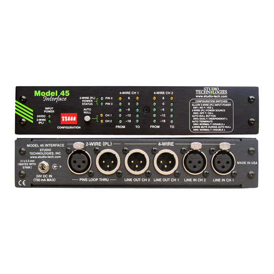
- Page 21 pin 2 falls below 24 volts for a continuous as a support aid during installation, con- 1- second interval. The hardware and figuration, operation, and troubleshooting. software responds to this condition by The meters represent the strength of the turning off the power source to pin 2 and signals coming in from, and going out to, flashing the pin 2 LED as a warning.
- Page 22 Auto Null device’s nominal level matches the Model 45’s level setting its actual nominal level The Model 45 contains circuitry to auto- may be significantly different. With a digital matically null the two 2-wire-to-4-wire matrix intercom system this problem could interfaces.
- Page 23 An auto null sequence begins with the to many user devices it may not apply to muting of the 4-wire input and output all. Muting microphones is significant as signal paths associated with the channel obtaining a “deep” null requires that no being nulled.
-
Page 24: Technical Notes
readily apparent. The front-panel LEDs will is interesting to “hear” the nulling process continue to display the DC power status of take place. But unless there’s a really good pins 2 and 3. But whether or not either or reason, configuration DIP switch 5 should both LEDs are lit, the Model 45 will never always remain in its off (down) position. - Page 25 Major Release Number Release Sub-Number .4 O .3 .2 O .1 O 1 Figure 8. Detail of front panel showing the status LEDs that display the software version. In this example, the software version is 1.3. Two Units can be a TW-12B Note that while it’s easy to determine which software version is loaded into Replacement...
- Page 26 unit. Power can be provided by the con- nected intercom circuits or by way of an external source of 24 volts DC. The final step to achieve correct performance is for the auto null function on each Model 45 to be activated.
-
Page 27: Specifications
Specifications Meters: 4 Function: displays level of 4-wire inputs and outputs General Audio: Type: 5-segment LED, modified VU ballistics Frequency Response: ±2.5 dB 100 Hz to 8 kHz Distortion (THD+N): <0.2%, measured at 1 kHz, Connectors: 4-wire input to 2-wire interface pin 2 4-Wire Line Inputs: 3-pin female XLR-type Signal-to-Noise Ratio: >55 dB, measured at 4-Wire Line Outputs: 3-pin male XLR-type... -
Page 28: Appendix A-Interfacing With Rts® Matrix Intercom Systems
Appendix A Interfacing RTS® Matrix Intercom Systems with the Model 45 Interface ADAM™ Matrix Intercom System Analog Ports to Model 45 Interface RVON-I/O I/O Connections to Model 45 Interface Issue Preliminary 2, March 2009 Model 45 User Guide Page 28 Studio Technologies, Inc. -
Page 29: Appendix B-Interfacing With Riedel® Artist™ Matrix Intercom Systems
Appendix B Interfacing Riedel® Artist™ Matrix Intercom System Analog Ports with the Model 45 Interface Model 45 User Guide Issue Preliminary 2, March 2009 Studio Technologies, Inc. Page 29... -
Page 30: Appendix C-Interfacing With Clear-Com® Matrix Intercom Systems
Appendix C Interfacing Clear-Com® Matrix Intercom System Analog Ports with the Model 45 Interface Issue Preliminary 2, March 2009 Model 45 User Guide Page 30 Studio Technologies, Inc. - Page 31 This page intentionally left blank. Model 45 User Guide Issue Preliminary 2, March 2009 Studio Technologies, Inc. Page 31...
Need help?
Do you have a question about the M45 Interface and is the answer not in the manual?
Questions and answers