
Related Manuals for Fluke NetTool II Series


Summary of Contents for Fluke NetTool II Series
- Page 1 NetTool Series II Inline Network Tester Getting Started Guide PN 2631943 September 2006 © 2006 Fluke Corporation. All rights reserved. Printed in USA. All product names are trademarks of their respective companies.
- Page 2 Resellers are not author- ized to extend any other warranty on Fluke Networks’ behalf. To obtain service during the warranty period, contact your nearest Fluke Networks authorized service...
-
Page 3: Table Of Contents
Inline Connection............19 AutoTest................20 Cable Test Results............21 Wiremap Test Results ..........21 Service Identification Test Results ......22 Device and Network Test Results ......22 NetTool Connect ............23 Updating the Software ..........23 Contacting Fluke Networks..........24... -
Page 5: About This Guide
NetTool Series II Inline Network Tester About This Guide We know that you want to begin using your new NetTool Series II Inline Network Tester right away. This guide provides basic information to help you do just that. The first section acquaints you with the features of your NetTool Series II Inline Network Tester (hereafter referred to as the tester) and provides quick, easy-to- follow instructions for setting it up. -
Page 6: Nettool Product Features
NetTool Product Features Your NetTool tester enables you to diagnose common Layer 1 – 7 problems, giving you total visibility into your network. Specifically, you can: • Troubleshoot cable problems • “Listen” to network traffic and gather information about PC and link configurations, network health, and key devices •... -
Page 7: Registering Your Nettool Tester
Please take the time to register your tester. Registration offers you access to support, training, software, and product updates. Go to the Fluke Networks website at http://www.flukenetworks.com. Click the Register link and follow the instructions to log in and register your tester online. -
Page 8: Power Supply
Power Supply To supply power to your tester, you can use batteries, the optional AC Adapter, or PoE. Using the Batteries and AC Adapter The tester uses four alkaline batteries (supplied) or four rechargeable NiMH batteries (optional). To install the batteries, remove the yellow boot to access the battery compartment. - Page 9 To use AC power, connect the AC adapter to the tester as shown in the following diagram: LC-3 LC-1 LC-4 Europe North American LC-7 LC-5 LC-6 South Africa Swiss Australia ekd02f.eps...
-
Page 10: Using Poe Power
Using PoE Power If the tester is connected to PSE and has negotiated power from the device, it uses power supplied by the PSE. Note You must use the left RJ-45 jack to connect the tester to a PoE switch. IEEE 803.3af PoE Switch ekd03f.eps... -
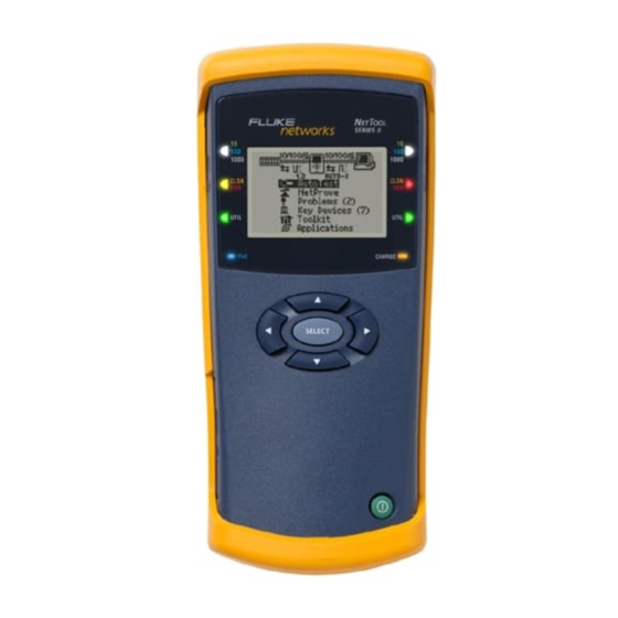
Page 11: Front View
Front View ekd04f.eps... - Page 12 Front Panel Buttons and LEDs Item Function Number Link LED for the left and right RJs • White: 1000 MB connection. • Blue: 100 MB connection. • Green: 10 MB connection. Collision/Error LED for the left and right • Yellow: collisions are occurring. •...
- Page 13 Front Panel Buttons and LEDs (cont) Item Function Number CHARGE LED • Steady green: batteries are fully charged, and the tester is plugged into external power. • Blinking green: batteries are more than 50 % full and charging. • Blinking orange: batteries are less than 50 % full and charging.
-
Page 14: Left Side View
Left Side View Left RJ-45 USB Port AC power ekd05f.eps Left RJ-45: Use the left RJ-45 jack for a single-ended connection (that is, when connecting the tester directly to a cable, a PC, an IP phone, wall drop, or a network device). -
Page 15: Navigation Buttons
Navigation Buttons The navigation keys encircle the SELECT key. These keys control the on-screen cursor and enable you to navigate through the menu system. SELECT ahn310f.eps Scrolling To scroll through a menu, press the Up and Down arrow keys. When the desired item is highlighted, press SELECT. -
Page 16: Menus
Menus After AutoTest runs, the top-level screen is displayed: NetTool Series II Icon Network Icon PC Icon Main Menu ekd06f.eps Network Diagram The network diagram at the top of the screen provides at-a-glance information about the connection. Link Speed Actual Link Speed (underlined) Link Level and Polarity Cable Status... - Page 17 The icons represent the connected devices: The NetTool icon is located in the center of the diagram. Select this icon to access the tester’s configuration screens. The Network and PC icons appear to the left or right of the NetTool icon, depending on how you connected the cable.
-
Page 18: Main Menu
Main Menu The Main menu is located under the connection diagram. From this menu, you can select the following: • AutoTest: automatically analyzes the connection at the RJ-45 jacks and displays results. • NetProve: automatically proves Ping and Application connectivity to servers and key devices. -
Page 19: Setting User Preferences
Setting User Preferences You may need to change some of the default configuration settings so that your tester fits your particular work environment and testing situations. From the Main menu: Select the NetTool icon to access the NetTool menu. Select Settings to view these options: •... -
Page 20: Connecting The Tester
Connecting the Tester The tester has two RJ-45 jacks, one on each side. For a single-ended connection, plug one end of a cable into the left jack and the other end directly into a wall plate to check a network drop or into a device such as PC, hub, or switch. -
Page 21: Patch Cable Test
Patch Cable Test ekd09f.eps Wiremap When both ends of a cable cannot be connected to the tester (for example, if one end is in a wiring closet), connect a wiremap adapter to the far end: NetTool Series II Inline Network Tester Wiremap ekd10f.eps... -
Page 22: Toner
Toner Note To access the Toner menu, click (the NetTool icon). IntelliTone NetTool Series II Probe Inline Network Tester ekd11f.eps... -
Page 23: Inline Connection
Inline Connection Note Use the left RJ to connect the tester to the network and the right RJ to connect to a PC or phone. Switch NetTool Series II Inline Network Tester ekd12f.eps... -
Page 24: Autotest
AutoTest When you run AutoTest, the tester searches the RJ-45 connections to determine what it is connected to and then displays results. To run AutoTest: Connect the NetTool tester as shown in one of the network diagrams presented earlier. Turn on the tester. The AutoTest screen is displayed: ahn13s.bmp If a device is connected, turn it on. -
Page 25: Cable Test Results
Cable Test Results After AutoTest ends, select the Spool icon . Then, press SELECT. The Cable screen displays the length of the cable and indicates whether any opens, shorts, or split pairs are detected. afq32s.bmp Wiremap Test Results After AutoTest ends, select the Wiremap icon Then press SELECT. -
Page 26: Service Identification Test Results
Service Identification Test Results After AutoTest ends, the tester displays the type of service that is active on the jack: • Telco • Ethernet • No Response: the tester detects the device but the device is not responding Device and Network Test Results After AutoTest completes, select the PC icon find out about the PC device: afq16s.bmp... -
Page 27: Nettool Connect
NetTool Connect NetTool Connect is a software utility that is located on the CD-ROM that is packaged with NetTool. This program enables you to do the following: • Install software updates on your NetTool tester • Download the tester’s screen captures to your PC •... -
Page 28: Contacting Fluke Networks
Contacting Fluke Networks www.flukenetworks.com support@flukenetworks.com +1-425-446-4519 • Australia: 61 (2) 8850-3333 or 61(3) 9329 0244 • Beijing: 86 (10) 6512-3435 • Brazil: 11 3044 1277 • Canada: 1-800-363-5853 • Europe: +44-(0) 1923 281 300 • Hong Kong: 852 2721-3228 •...
Need help?
Do you have a question about the NetTool II Series and is the answer not in the manual?
Questions and answers