Table of Contents
Advertisement
Available languages
Available languages
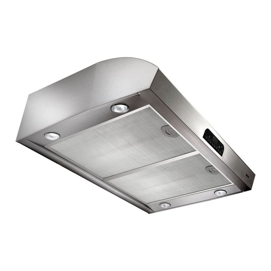
EVOLUTION
QP4 Series Range Hoods
READ AND SAVE THESE INSTRUCTIONS
WARNING
TO REDUCE THE RISK OF FIRE, ELECTRIC SHOCK, OR
INJURY TO PERSONS, OBSERVE THE FOLLOWING:
1. Use this unit only in the manner intended by the manufacturer.
If you have questions, contact the manufacturer at the address
or telephone number listed in the warranty.
2. Before servicing or cleaning unit, switch power off at service
panel and lock the service disconnecting means to prevent
power from being switched on accidentally. When the service
disconnecting means cannot be locked, securely fasten a
prominent warning device, such as a tag, to the service panel.
3. Installation work and electrical wiring must be done by a
qualified person(s) in accordance with all applicable codes
and standards, including fire-rated construction.
4. Sufficient air is needed for proper combustion and exhausting
of gases through the flue (chimney) of fuel burning equipment
to prevent backdrafting. Follow the heating equipment
manufacturer's guideline and safety standards such as those
published by the National Fire Protection Association (NFPA),
and the American Society of Heating, Refrigeration and
Air Conditioning Engineers (ASHRAE), and the local code
authorities.
5. This product may have sharp edges. Be careful to avoid cuts
and abrasions during installation and cleaning.
6. When cutting or drilling into wall or ceiling, do not damage
electrical wiring and other hidden utilities.
7. Ducted fans must always be vented to the outdoors.
8. Use only metal ductwork.
9. Do not use this fan with any solid-state speed control device.
10. As an alternative, this product may be installed with the
UL-approved cord kit designated for the product, following
instructions packed with the cord kit.
11. This unit must be grounded.
TO REDUCE THE RISK OF A RANGE TOP GREASE FIRE:
1. Never leave surface units unattended at high settings.
Boilovers cause smoking and greasy spillovers that may
ignite. Heat oils slowly on low or medium settings.
2. Always turn hood ON when cooking at high heat or when
flambéing food (i.e. Crepes Suzette, Cherries Jubilee,
Peppercorn Beef Flambé).
3. Clean ventilating fans frequently. Grease should not be
allowed to accumulate on fan or filter.
4. Use proper pan size. Always use cookware appropriate for the
size of the surface element.
TO REDUCE THE RISK OF INJURY TO PERSONS IN THE
EVENT OF A RANGE TOP GREASE FIRE, OBSERVE THE
FOLLOWING:*
1. SMOTHER FLAMES with a close-fitting lid, cookie sheet,
or metal tray, then turn off the burner. BE CAREFUL TO
PREVENT BURNS. If the flames do not go out immediately,
EVACUATE AND CALL THE FIRE DEPARTMENT.
4
TM
FOR DOMESTIC COOKING ONLY
MODELS QP430SS • QP436SS • QP442SS
WARNING
2. NEVER PICK UP A FLAMING PAN — You may be burned or
spread the fire.
3. DO NOT USE WATER, including wet dishcloths or towels - a
violent steam explosion will result.
4. Use an extinguisher ONLY if:
A. You know you have a Class ABC extinguisher, and you
already know how to operate it.
B. The fire is small and contained in the area where it started.
C. The fire department is being called.
D. You can fight the fire with your back to an exit.
* Based on "Kitchen Firesafety Tips" published by NFPA.
CAUTION
1. For indoor use only.
2. For general ventilating use only. Do not use to exhaust
hazardous or explosive materials and vapors.
3. To avoid motor bearing damage and noisy and/or unbalanced
impeller, keep drywall spray, construction dust, etc., off power
unit.
4. Do not use over cooking equipment greater than 70,000
BTU/hr. as the blower motor will shut down intermittantly.
5. Your hood motor has a thermal overload which will
automatically shut off the motor if it becomes overheated. The
motor will restart when it cools down. If the motor continues
to shut off and restart, have the hood serviced.
6. The top of the hood MUST NOT BE LESS than 30" and at a
maximum of 36" above cooktop for best capture of cooking
impurities.
7. This hood is not intended to be used as a shelf.
8. Please read specification label on product for further
information and requirements.
Register your product online at: www.broan.com
Installer: Leave this manual
with the homeowner.
Homeowner: Cleaning, Maintenance and
Operating instructions on page 2.
Page 1
Advertisement
Table of Contents

Subscribe to Our Youtube Channel
Related Manuals for Broan EVOLUTION QP430SS


Summary of Contents for Broan EVOLUTION QP430SS
- Page 1 6. The top of the hood MUST NOT BE LESS than 30” and at a maximum of 36” above cooktop for best capture of cooking impurities. 7. This hood is not intended to be used as a shelf. 8. Please read specification label on product for further information and requirements. Homeowner: Cleaning, Maintenance and already know how to operate it. Register your product online at: www.broan.com Installer: Leave this manual with the homeowner. Operating instructions on page 2. Page 1...
-
Page 2: Operation
CONTENTS INCLUDED WITH THE HOOD: GREASE FILTERS (2 - FOR 30” & 36” HOODS) (3 - FOR 42” HOODS) HALOGEN BULBS (1) VERTICAL AIR DIVERTER (1) PARTS BAG CONTAINING: WIRE NUTS #8 X 1/4” DUCT CONNECTOR SCREWS CLEANING & MAINTENANCE For performance, appearance, and health reasons, clean filter, fan and grease-laden surfaces. Use only a clean cloth and mild detergent solution on stainless and painted surfaces. -
Page 3: Timer/Clock Settings
10-MINUTE DELAY OFF When your hood fan is on (any speed) press the activate the delay off feature. When activated, the hood fan will automatically turn off after 10-minutes has elapsed. The delay feature is active when the following appear on the LED screen: A green indicator illuminated above the delay countdown “10-0” , and a clockwise rotating LED. The delay button can be pressed once again, to stop the delay countdown. Pressing the button again will resume the delay countdown. Pressing and holding the button will turn off the feature. TIMER Press the button to activate the timer setting feature. Use the and buttons to reduce or advance the timer setting to the desired duration. When the desired timer setting is reached, allow 3 seconds without pressing any additional button or press the button once again. The timer will then activate, and the countdown will be displayed on the LED screen along with an green indicator above the button. After the timer has... -
Page 4: Fuses
The hood is compatible with Broan Make-Up Air Damper Model MD6T or Model MD8T (optional). Purchase separately. Make the connection to the Make-Up Air Damper with low voltage wiring, as shown. See Make-Up Air Damper instructions for additional information. LOW-VOLTAGE CONNECTOR FOR MAKE-UP AIR DAMPER LIGHT FUSE REMOTE CONTROL The hood is compatible with Broan RF Remote Control Model BCR1 (optional). Purchase separately. BACK OF HOOD RANGE MAKE-UP AIR HOOD DAMPER LOW-VOLTAGE WIRES DAMPER MOTOR... -
Page 5: Prepare Hood Location
PREPARE HOOD LOCATION ROOF CAP 3¼" X 14" or 7" ROUND DUCT (For vertical discharge) SOFFIT CABINET HOOD HOOD 30" - 36" ABOVE COOKING SURFACE Determine whether hood will discharge vertically (3¼” x 14” or 7” Round), or horizontally (3¼” x 14” only). For vertical or horizontal discharge, run ductwork between the hood location and a roof cap or wall cap. For best results, use a minimum number of transitions and elbows. Use the proper diagram, as follows, for placement of ductwork and electrical cutout in cabinet or wall. VERTICAL DISCHARGE DUCT & ELECTRICAL CUTOUTS CABINET FRONT CABINET BOTTOM "... -
Page 6: Prepare The Hood
PREPARE THE HOOD Remove parts bag and 3¼” x 14” damper/duct connector from inside the hardware box included with the hood. Remove all protective polyfilm from the hood. Remove 6 Screws holding Bottom Pan to hood. Set bot- tom pan and screws aside. SCROLL BUSHING SCREWS LEFT-HAND LIGHT PANEL FOR 30” MODEL ONLY: Remove Left-Hand Light Panel by removing (2) Screws and disconnecting electrical connector. Remove Rubber Bushing in Scroll Cap. Set parts aside. 3¼” X 14” HORIZONTAL KNOCKOUT PLATE Remove 3¼” x 14” vertical, 3¼” x 14” horizontal, or 7-inch round Knockout Plate(s) as appropriate for your ducting method. MODELS QP430SS • QP436SS • QP442SS TOP/BACK EDGE OF HOOD... -
Page 7: Install The Hood
INSTALL THE HOOD WARNING To reduce the risk of electrical shock, switch power off at service panel. Lock or tag service panel to prevent power from being switched on accidentally. ELECTRICAL POWER CABLE KNOCKOUT Remove Electrical Wiring Box Cover from inside 10 of hood and appropriate Electrical Power Cable Knockout from top or back of hood. HOUSE POWER CABLE Run House Power Cable between service panel and hood location. Attach power cable to hood using appropriate clamp. Hang hood from (4) mounting screws driven part-way into cabinet locations (shown in illustrations under “PREPARE HOOD LOCATION”). Mounting screws are included in parts bag. Slide hood back towards wall until mounting screw heads are engaged in narrow end of keyhole slots in top of hood. Tighten screws securely. Add 5th mounting screw in center hole in hood and tighten securely. Connect ductwork to hood and use duct tape to make joints secure and air-tight. Make sure the damper / duct connector enters the ductwork and that the damper opens and closes freely. MODELS QP430SS • QP436SS • QP442SS CONNECT THE WIRING GROUND SCREW... -
Page 8: Service Parts
REMEDY UNDER THIS WARRANTY. BROAN-NUTONE SHALL NOT BE LIABLE FOR INCIDENTAL, CONSEQUENTIAL OR SPECIAL DAMAGES ARISING OUT OF OR IN CONNECTION WITH PRODUCT USE OR PERFORMANCE. Some states do not allow the exclusion or limitation of incidental or consequential damages, so the above limitation or exclusion may not apply to you. This warranty gives you specific legal rights, and you may also have other rights, which vary from state to state. This warranty supersedes all prior warranties. To qualify for warranty service, you must (a) notify Broan-NuTone at the address or telephone number below, (b) give the model number and part identification and (c) describe the nature of any defect in the product or part. At the time of requesting warranty service, you must present evidence of the original purchase date. Broan-NuTone LLC, 926 W. State Street, Hartford, Wisconsin 53027 www.broan.com 800-558-1711 MODELS QP430SS • QP436SS • QP442SS... - Page 9 6. Pour mieux capter les vapeurs de cuisson, le bas de la hotte DOIT ÊTRE AU MINIMUM à 76 cm (30 po) et au maximum à 91 cm (36 po) au-dessus de la surface de cuisson 7. Cette hotte n’est pas conçue pour servir d’étagère. 8. Veuillez lire l’étiquette de spécifications du produit pour obtenir plus de renseignements, notamment sur les exigences. Enregistrez votre produit en ligne à : www.broan.com. mode de fonctionnement. Installateur : Veuillez remettre ce manuel au propriétaire. Propriétaire : Nettoyage, entretien et mode d’emploi à la page 10.
-
Page 10: Nettoyage Et Entretien
CONTENU INCLUS AVEC LA HOTTE : FILTRES À GRAISSES [2 - POUR LES HOTTES DE 76 CM (30 PO) ET 91 CM (36 PO) 3 - POUR LES HOTTES DE 106 CM (42 PO)] AMPOULES HALOGÈNES (1) RÉPARTITEUR D’ A IR VERTICAL (1) SACHET DE PIÈCES CONTENANT : VIS N°... - Page 11 ARRÊT DIFFÉRÉ DE 10 MINUTES La hotte étant en marche (à n’importe quelle vitesse), appuyez sur le bouton pour activer la fonction d’arrêt différé. Le ventilateur s’arrêtera automatiquement après un délai de 10 minutes. La fonction d’arrêt différé est active lorsque ce qui suit apparaît sur l’écran DEL : Un témoin vert s’allume au- dessus du bouton d’arrêt différé « 10 à 0 » s’affiche ainsi que des DEL s’allument en tournant dans le sens horaire. Appuyez de nouveau sur le bouton d’arrêt différé...
- Page 12 2. Enlevez les filtres et le panneau inférieur. 3. Enlevez et inspectez le fusible. S’il n’a pas sauté (grillé), un diagnostic plus poussé doit être effectué. MODÈLES QP430SS • QP436SS • QP442SS CLAPET D’AIR DE COMPENSATION La hotte est compatible avec le Clapet d’air de compensation Broan modèle MD6T ou modèle MD8T (en option). Vendu séparément. Connectez le clapet d’air de compensation avec les fils de basse tension, tel qu’illustré. Pour de plus amples renseignements, con- sultez les directives du clapet d’air de compensation. FUSIBLE DE L’ÉCLAIRAGE TÉLÉCOMMANDE...
- Page 13 PRÉPARATION DE L’EMPLACEMENT DE LA HOTTE CAPUCHON CONDUIT de 8,2 cm DE TOIT (3¼ po) x 35,5 cm (14 po) ou CONDUIT ROND de 18 cm (7 po) (Pour évacuation verticale) SOFFITE ARMOIRE HOTTE HOTTE 76 à 91 CM (30 à 36 PO) AU-DESSUS DE LA SURFACE DE CUISSON Déterminez si la sortie de la hotte sera verticale [conduit de...
-
Page 14: Préparation De La Hotte
PRÉPARATION DE LA HOTTE Retirez le sachet de pièces et le clapet / raccord de conduit 8,2 (3¼ po) X 35,5 cm (14 po) de la boîte de quincaillerie incluse avec la hotte. Enlevez toutes les pellicules protectrices de la hotte. Enlevez les six vis maintenant le panneau inférieur de la hotte. Mettez le panneau inférieur et les vis de côté. COUVERCLE DE DÉFILEMENT MANCHON PANNEAU D’ÉCLAIRAGE GAUCHE POUR MODÈLE 76 CM (30 PO) UNIQUEMENT : Retirez le panneau d’éclairage gauche en enlevant les deux (2) vis et en débranchant le connecteur électrique. Enlevez le manchon en caoutchouc du couvercle de défilement. Mettez les pièces de côté. PLAQUE VERTICALE PRÉAMORCÉE DE 8,2 cm (3¼ po) X 35,5 cm (14 po) Enlevez la plaque verticale préamorcée de 8,2 cm (3¼ po) x 35,5 cm (14 po), la plaque horizontale préamorcée de 8,2 cm (3¼ po) x 35,5 cm (14 po), ou la plaque ronde préamorcée de... -
Page 15: Installation De La Hotte
INSTALLATION DE LA HOTTE AVERTISSEMENT Pour réduire les risques de choc électrique, coupez le courant du panneau électrique. Verrouillez ou posez un sceau sur le panneau afin d’éviter que le courant ne soit rétabli accidentellement. OUVERTURE PRÉAMORCÉE DU CÂBLE D’ A LIMENTATION ÉLECTRIQUE Enlevez le couvercle du boîtier de connexion 10 électrique à l’intérieur de la hotte et l’ouverture préamorcée de câble d’alimentation électrique appropriée sur le dessus ou à l’arrière de la hotte. CÂBLE ÉLECTRIQUE DE LA MAISON Acheminez le fil d’alimentation électrique du panneau électrique jusqu’à l’emplacement de la hotte. Fixez le câble à la hotte avec le connecteur approprié. Suspendez la hotte à l’aide de (4) vis à moitié vissées aux endroits marqués sous l’armoire (illustré sous « PRÉPARATION DE L’EMPLACEMENT DE LA HOTTE »). Ces vis sont incluses dans le sac de pièces. Glissez la hotte vers le mur de manière à engager la tête des vis dans la fente des trous de serrure du dessus de la hotte. Resserrez fermement les vis. Ajoutez la cinquième vis de montage dans le trou central de la hotte et serrez-la fermement. -
Page 16: Garantie
Certains territoires ou provinces interdisant de limiter la durée d’une garantie tacite, la limitation ci-dessus peut ne pas s’appliquer à votre situation. L’OBLIGATION POUR BROAN-NUTONE DE RÉPARER OU DE REMPLACER LE PRODUIT, À SA DISCRÉTION, CONSTITUE LE SEUL RECOURS DE L’ACHETEUR EN VERTU DE LA PRÉSENTE GARANTIE. BROAN-NUTONE NE PEUT ÊTRE TENUE RESPONSABLE DES DOMMAGES INDIRECTS OU CONSÉCUTIFS NI DES DOMMAGES-INTÉRÊTS PARTICULIERS... - Page 17 7. Esta campana no está diseñada para usarse como repisa. 8. Lea la etiqueta de especificaciones que tiene el producto para ver información y requisitos adicionales. Registre su producto en Internet en: www.broan.com Aviso al dueño de la casa: En la página 18 encontrará las instrucciones de limpieza, Aviso al instalador: Deje este manual con el dueño de la casa.
-
Page 18: Limpieza Y Mantenimiento
CONTENIDO SE INCLUYE CON LA CAMPANA: FILTROS PARA GRASA 2 PARA LAS CAMPANAS DE 30 Y 36 PULG. (76 Y 91 CM) Y 3 PARA LAS CAMPANAS DE 42 PULG. (106 CM) BOMBILLAS DE HALÓGENO (1) DESVIADOR DE AIRE VERTICAL (1) BOLSA DE PIEZAS QUE CONTIENE TORNILLOS TUERCAS... - Page 19 APAGADO CON RETARDO DE 10 MINUTOS Cuando el ventilador de la campana esté encendido (en cualquier velocidad), presione el botón función de apagado con retardo. Cuando se activa, el ventilador de la campana se apagará automáticamente después de que transcurran 10 minutos. Esta función se activa cuando aparece lo siguiente en la pantalla de diodos LED: Un indicador verde iluminado arriba del botón de retardo descendente (10 a 0) y un LED que gira hacia la derecha.
- Page 20 2. Retire los filtros y el recipiente inferior. 3. Quite y revise el fusible. Si no está abierto (fundido), necesitará realizar diagnósticos adicionales. MODELOS QP430SS • QP436SS • QP442SS REGULADOR DE AIRE DE REPUESTO La campana es compatible con el regulador de aire de repuesto Broan, Modelo MD6T o Modelo MD8T (opcional). Se compra por separado. Realice la conexión del regulador de aire de repuesto con ca- bleado de bajo voltaje, como se ilustra. Consulte información adicional en las instrucciones del regulador de aire de repuesto. CONECTOR DE BAJO VOLTAJE PARA EL REGULADOR DE AIRE DE REPUESTO...
- Page 21 PREPARE EL LUGAR DONDE SE VA A INSTALAR LA CAMPANA CONDUCTO DE 3¼ x TAPA DE TECHO 14 pulg. (8.2 x 35.5 cm) o REDONDO de 7 pulg. (18 cm) (para descarga vertical) PLAFÓN GABINETE CAMPANA CAMPANA 30 a 36 pulg. (76 a 91 cm) POR ARRIBA DE LA SUPERFICIE PARA COCINAR Determine si la descarga de la campana va a ser vertical...
-
Page 22: Prepare La Campana
PREPARE LA CAMPANA Retire la bolsa con piezas y el conector para regulador/ conducto de 3¼ x 14 pulg. (8.2 x 35.5 cm) del interior de la caja de herrajes, incluida con la campana. Retire toda la película protectora de polietileno de la campana. Quite los 6 tornillos que sostienen el recipiente inferior a la campana. Deje a un lado el recipiente inferior y los tornillos. TAPA DESLIZANTE BUJE TORNILLOS PANEL DE LUCES DEL LADO IZQUIERDO SÓLO PARA EL MODELO DE 30 PULG. (76 CM): Retire el panel de luces del lado izquierdo quitando dos (2) tornillos y desconectando el conector eléctrico. Quite el buje de caucho en la tapa deslizante. Deje las piezas a un lado. PLACA VERTICAL DE AGUJERO CIEGO DE 3¼ X 14 PULG. -
Page 23: Instale La Campana
INSTALE LA CAMPANA ADVERTENCIA Para reducir el riesgo de una descarga eléctrica, desconecte el suministro eléctrico en el panel de servicio. Bloquee el panel de servicio o póngale una etiqueta de seguridad para evitar que alguien conecte accidentalmente la energía eléctrica. ORIFICIO CIEGO DEL CABLE ELÉCTRICO 10 Quite la cubierta de la caja de cableado eléctrico del interior de la campana y el agujero ciego correspondiente del cableado eléctrico desde la parte superior o trasera de la campana. CABLE ELÉCTRICO DE LA CASA Tienda el cable eléctrico de la casa entre el panel de servicio y la campana. Conecte el cable eléctrico a la campana con la abrazadera apropiada. Cuelgue la campana de los (4) orificios de montaje insertados parcialmente en las posiciones del gabinete (mostrado en las ilustraciones de “PREPARE EL LUGAR DONDE SE VA A INSTALAR LA CAMPANA”). La bolsa de piezas contiene los tornillos de montaje. Deslice la campana hacia la pared hasta que las cabezas de los tornillos de montaje queden conectadas en el extremo angosto de los orificios tipo bocallave que están en la parte superior de la campana. -
Page 24: Piezas De Servicio
DAÑOS INCIDENTALES, CONSECUENTES, O POR DAÑOS ESPECIALES QUE SURJAN A RAÍZ DEL USO O DESEMPEÑO DEL PRODUCTO. Algunos estados no permiten la exclusión o limitación de daños incidentales o consecuentes, por lo que la limitación antes mencionada puede no aplicarse a usted. Esta garantía le proporciona derechos legales específicos, y usted puede también tener otros derechos, los cuales varían de estado a estado. Esta garantía reemplaza todas las garantías anteriores. Para calificar para la garantía de servicio, usted debe (a) notificar a Broan-NuTone al domicilio o al número de teléfono que se menciona abajo, (b) dar el número del modelo y la identificación de la pieza, y (c) describir la naturaleza de cualquier defecto en el producto o la pieza. En el momento de solicitar servicio cubierto por la garantía, usted debe de presentar un comprobante con la fecha original de compra. Broan-NuTone LLC, 926 W. State Street, Hartford, Wisconsin 53027 www.broan.com 800-558-1711 Broan-NuTone Canada, Inc., 1140 Tristar Drive, Mississauga, Ontario L5T 1H9 www.broan.ca 877-896-1119...
Need help?
Do you have a question about the EVOLUTION QP430SS and is the answer not in the manual?
Questions and answers