Table of Contents
Advertisement
Quick Links
CAN-PCI/331
Vahrenwalder Str. 207 • 30165 Hannover • Germany
Vahrenwalder Str. 207 • 30165 Hannover • Germany
Phone: +49 (0) 511 3 72 98-0 • Fax: +49 (0) 511 3 72 98-68
Phone: +49 (0) 511 3 72 98-0 • Fax: +49 (0) 511 3 72 98-68
CAN-PCI/331
PCI-CAN-Interface
DN-PCI/331
PCI-DeviceNet-Interface
Hardware Manual
to Product C.2020.xx
Hardware Manual • Doc. No.: C.2020.21 / Rev. 1.6
esd electronic system design gmbh
esd electronic system design gmbh
http://www.esd.eu
http://www.esd.eu
and C.2017.xx
Page 1 of 27
Advertisement
Table of Contents

Related Manuals for ESD CAN-PCI/331


Summary of Contents for ESD CAN-PCI/331
- Page 1 CAN-PCI/331 Hardware Manual • Doc. No.: C.2020.21 / Rev. 1.6 Page 1 of 27 esd electronic system design gmbh esd electronic system design gmbh Vahrenwalder Str. 207 • 30165 Hannover • Germany Vahrenwalder Str. 207 • 30165 Hannover • Germany http://www.esd.eu...
- Page 2 The information in this document has been carefully checked and is believed to be entirely reliable. esd makes no warranty of any kind with regard to the material in this document, and assumes no responsibility for any errors that may appear in this document. In particular descriptions and technical data specified in this document may not be constituted to be guaranteed product features in any legal sense.
- Page 3 1.1” (see print at PCB top layer corner) on only. Figure “Top layer view of the DN-PCI/331-2” inserted. 2014-01-27 Chapter “LED description” inserted. 2014-01-27 Reference voltage of electrical isolation of CAN-PCI/331 inserted. 2013-12-27 Shield not connected at DN-PCI/331 with order no. C.2017.06 and C.2017.07 2013-12-27 Update of order information.
- Page 4 Do not operate the CAN-PCI/331 adjacent to heat sources and do not expose it to unnecessary thermal radiation. Ensure an ambient temperature as specified in the technical data. Do not use damaged or defective cables to connect the CAN-PCI/331 and follow the CAN wiring hints in chapter: "Correctly Wiring Electrically Isolated CAN Networks".
-
Page 5: Table Of Contents
3.2 PCI-Bus..........................10 CAN/DeviceNet Interface.....................11 Software Support......................... 11 LED Description (DN-PCI/331 only)...................12 Connector Assignments......................13 CAN (CAN-PCI/331 only).....................13 DeviceNet Interface (DN-PCI/331 only)................14 Correct Wiring of Electrically Isolated CAN Networks..............15 Standards concerning CAN Wiring..................15 Heavy Industrial Environment (Double Twisted Pair Cable)..........16 6.2.1... -
Page 6: Overview
+5 V= Figure 1: Block circuit diagram of CAN-PCI/331 The CAN-PCI/331 is an intelligent PC card for PCI-bus systems. It is equipped with a MC68331 microcontroller, that controls the CAN data locally. The microcontroller buffers the CAN data in a local SRAM. -
Page 7: Description Of The Dn-Pci/331
+24 V= DC/DC Converter +5 V= Figure 2: Block circuit diagram of DN-PCI/331 The DeviceNet interface of the DN-PCI/331 meets the requirements of the DeviceNet specification 2.0. CAN-PCI/331 Hardware Manual • Doc. No.: C.2020.21 / Rev. 1.6 Page 7 of 27... -
Page 8: Pcb View With Connectors
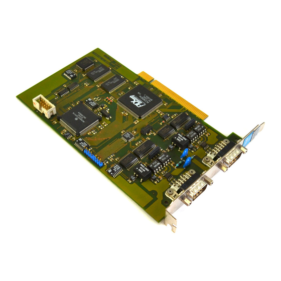
Overview 1.3 PCB View with Connectors Figure 3: Top layer view of the CAN-PCI/331-2 module with 2x CAN Figure 4: Top layer view of the DN-PCI/331-2 module with 2x DeviceNet Page 8 of 27 Hardware Manual • Doc. No.: C.2020.21 / Rev. 1.6... -
Page 9: Hardware Installation
Close the computer case again. Connect the network cable. CAN-PCI/331: Please note the wiring hints in chapter Fehler: Referenz nicht gefunden. The first CAN interface (CAN net 0) has to be connected via the lower DSUB connector (X401) and the second CAN interface (CAN net 1) has to be connected via the upper DSUB connector (X400). -
Page 10: Technical Data
PCI bus width 32 bit Controller PLX 9050 Interrupt interrupt signal A no restrictions for the position of the CAN-PCI/331 on the PCI bus, Slot position PCI bridges are tolerated Board dimensions compatible with all 'short' PCI-card slots Connector PCI-card edge connector... -
Page 11: Can/Devicenet Interface
Bus termination terminating resistor has to be set externally separation by means of optocouplers and DC/DC-converters Electrical separation of CAN interfaces from CAN-PCI/331: voltage over CAN isolation other units and from (CAN to slot bracket/EARTH; each other CAN to host/system ground;... -
Page 12: Led Description (Dn-Pci/331 Only)
Communication faulted state. DN-PCI/331 has Request- subsequently received and accepted an Identify Long Protocol Communication Faulted Request- Long Protocol message (not yet implemented) Table 4: DeviceNet module/network status LED description Page 12 of 27 Hardware Manual • Doc. No.: C.2020.21 / Rev. 1.6 CAN-PCI/331... -
Page 13: Connector Assignments
Connector Assignments 5. Connector Assignments 5.1 CAN (CAN-PCI/331 only) The signal assignments of CAN-net 0 (X400) and of the optional CAN-net 1 (X401) are identical. Device connector: 9-pin DSUB connector, male Pin Position: Pin Assignment: Signal Signal reserved (CAN_GND) CAN_L... -
Page 14: Devicenet Interface (Dn-Pci/331 Only)
Signal Description: V+... power supply (U = 24 V ± 4%) V-... reference potential to V+ and to CAN+/CAN- CAN+, CAN-... CAN-signals Shield... Shielding (internally not connected) Page 14 of 27 Hardware Manual • Doc. No.: C.2020.21 / Rev. 1.6 CAN-PCI/331... -
Page 15: Correct Wiring Of Electrically Isolated Can Networks
Therefore the practical maximum number of nodes, bus length and stub length are typically much lower. esd has concentrated her recommendations concerning CAN wiring on the specifications of the ISO 11898-2. Thus this wiring hints forgoes to describe the special features of the derived standards CANopen, ARINC825, DeviceNet and NMEA2000. -
Page 16: Heavy Industrial Environment (Double Twisted Pair Cable)
6.2 Heavy Industrial Environment (Double Twisted Pair Cable) 6.2.1 General Rules Note: esd only grants the compliance with directive 2004/108/EU, if the CAN wiring is carried out with single shielded double twisted pair cables that match the requirements of ISO 11898-2. -
Page 17: Device Cabling
DSUB9 connector from ERNI (ERBIC CAN BUS MAX, order no.:154039). The usage of esd’s T-connector type C.1311.03 is not recommended for single shielded double twisted pair cables because the shield potential of the conductive DSUB housing is not looped through this T-connector type. -
Page 18: Light Industrial Environment (Single Twisted Pair Cable)
6.3.1 General Rules Note: esd only grants the compliance with directive 2004/108/EU, if the CAN wiring is carried out with single shielded double twisted pair cables that match the requirements of ISO 11898-2. See previous chapter: 'Heavy Industrial Environment (Double Twisted Pair Cable)'. -
Page 19: Cabling
9-pin DSUB-termination connectors with integrated termination resistor and male and ● female contacts (gender changer) are available from esd (order no. C.1303.01). DSUB termination connectors with male contacts (order no. C.1302.01) or female contacts ● (order no. C.1301.01) and additional functional earth contact are available, if CAN termination and grounding of CAN_GND is required. -
Page 20: Electrical Grounding
5000 Table 5: Recommended cable lengths at typical bit rates (with esd-CAN interfaces) Optical couplers are delaying the CAN signals. esd modules typically reach a wire length of ● 37 m at 1 Mbit/s within a proper terminated CAN network without impedance disturbances like e.g. -
Page 21: Examples For Can Cables
Correct Wiring of Electrically Isolated CAN Networks 6.6 Examples for CAN Cables esd recommends the following two-wire and four-wire cable types for CAN network design. These cable types are used by esd for ready configured CAN cables, too. 6.6.1 Cable for light industrial Environment Applications (Two-Wire) -
Page 22: Can Troubleshooting Guide
- there are no open circuits in CAN_H or CAN_L wiring - your bus system has two terminating resistors (one at each end) and that they are 120 Ω each. Page 22 of 27 Hardware Manual • Doc. No.: C.2020.21 / Rev. 1.6 CAN-PCI/331... -
Page 23: Electrical Grounding
(see figure at previous page). 4. Measure the DC voltage between CAN_L and CAN_GND (see figure at previous page). Normally the voltage should be between 2.0 V and 3.0 V. CAN-PCI/331 Hardware Manual • Doc. No.: C.2020.21 / Rev. 1.6 Page 23 of 27... -
Page 24: Can Transceiver Resistance Test
If you have executed the fault diagnostic steps of this troubleshooting guide and you even can not find a solution for your problem our support department will be able to assist. Please contact our support via email at support@esd.eu or by phone +40-511-37298-130. Page 24 of 27 Hardware Manual •... -
Page 25: Declaration Of Conformity
Declaration of Conformity 8. Declaration of Conformity CAN-PCI/331 Hardware Manual • Doc. No.: C.2020.21 / Rev. 1.6 Page 25 of 27... -
Page 26: Order Information
Windows-XP object code, J1939 simulation tool, C.1130.10 esd CAN Windows driver license J1939 Stack for esd-CAN hardware, includes J1939 Stack for Linux Linux object code, esd CAN driver license for C.1130.11 Linux J1939 Stack for esd-CAN hardware, includes J1939 Stack for RTX RTX object code, esd CAN driver license for C.1130.12... - Page 27 Order Information PDF Manuals Manuals are available in English and usually in German as well. For availability of English manuals see table below. Please download the manuals as PDF documents from our esd website www.esd.eu for free. Manuals Order No.
Need help?
Do you have a question about the CAN-PCI/331 and is the answer not in the manual?
Questions and answers