Table of Contents
Advertisement
Quick Links
Advertisement
Table of Contents

Summary of Contents for LTS VSIP7643W-SZ
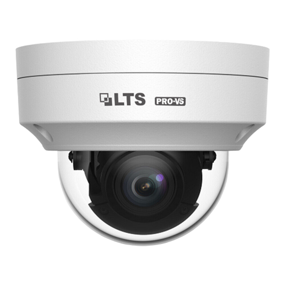
- Page 1 Network Fixed Dome Cameras Quick Guide...
-
Page 2: Safety And Compliance Information
Safety and Compliance Information Installation and removal of the unit and its accessories must be carried out by qualified personnel. You must read all of the Safety Instructions supplied with your equipment before installation and operation. Installation This device is a class A product and may cause radio interference. ... - Page 3 components for the RJ45 plug must be used properly to protect the network cable from water. Make sure the wall or ceiling is strong enough to support the weight of the camera. If dust falls during mounting, take off the dome cover and keep it away from dust.
-
Page 4: Regulatory Compliance
Make sure the lens cleaning cloth is clean itself. Never look at the transmit laser while the power is on. Never look directly at the fiber ports and the fiber cable ends when they are powered on. Use of controls or adjustments to the performance ... -
Page 5: Default Ip, Username And Password
LVD/EMC Directive This product complies with the European Low Voltage Directive 2014/35/EU and EMC Directive 2014/30/EU. WEEE Directive–2012/19/EU The product this manual refers to is covered by the Waste Electrical & Electronic Equipment (WEEE) Directive and must be disposed of in a responsible manner. - Page 6 Item Quantity Camera User document Accessory pack Appearance Dimensions The figures in the manual are for your reference only. The actual appearance may vary with the product model. Type A Ø 128.1mm (5.04") Ø 89.3mm (3.52") Type B...
-
Page 7: Cable Connection
Ø 128.1mm (5.04") Ø 89.3mm (3.52") Cable Connection The appearance and tail cable may vary with device model. The following examples show cables that are for 12 VDC.( for cameras with cable) Description Description Audio input/Audio Power interface output/GND... -
Page 8: Internal Structure
Description Description Alarm input/GND Ethernet interface / Alarm output(N,P) For specifications, see the latest product datasheets. Internal Structure Transparent dome cover Reset button Network Micro SD interface Card slot Safety wire Power interface Description Description... -
Page 9: Ceiling Mount
Description Description ALARM_OUTPUT_ ALARM_OUTPUT_P ALARM_INPUT AUDIO_IN AUDIO_OUT Use a pin to press and hold the Reset button for about 15 seconds to restore factory default settings. Perform this operation within 10 minutes after the device is powered on or the reset will fail otherwise. Mount Your Camera Ceiling Mount The following part takes ceiling mount as an example. - Page 10 1. Locate the holes, drill holes on the ceiling, and then mount the plastic rivets of self-tapping screws. See template for right direction of logo and tail cable. Paste the drill template and lead the cables through the hole. Use a Ø 6mm- 6.5mm drill bit to drill 30 mm-depth guide holes according to the template.
- Page 11 3. Mount your camera. Connect all cables of the ceiling and your camera Lead self-tapping screws through the guide holes in the camera base, and fix your camera on the ceiling by using a screwdriver Adjust the monitoring direction of the lens. Tighten the screws after vertically adjusting the lens.
- Page 12 Lens base Rotate the lens base horizontally. Fastening screw Loosen the fastening screws and rotate the lens vertically. Lens Rotate the lens horizontally. The above steps are only applied to the camera with manual zoom lens. For how to adjust the display of the camera with motorized zoom lens, please see the Web of the camera.
- Page 13 Mount the transparent dome cover. Align the screw holes in the base and tighten the three torx screws on the edge of the transparent dome cover to fix it...
-
Page 14: Access Your Camera
The preceding installation process is concealed installation, during which holes are drilled in the ceiling and tail cable is led out from the top of your camera. Cables are connected and frapped at the ceiling side to prevent messy cables from affecting camera mounting. - Page 15 Enter the username and password and then click Login. Install the ActiveX at your first login. When the installation of the ActiveX is completed, open your IE to log in. For your first login with Windows 7, if the system ...


Need help?
Do you have a question about the VSIP7643W-SZ and is the answer not in the manual?
Questions and answers