Table of Contents
Advertisement
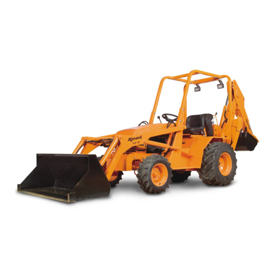
TLB 220, TLB 225, TLB 325,
TLB 425 ESL AND TLB 535 ESL
PHONE: 308/995-4495, 1-800/562-1373
ALLMAND PARTS FAX: 308/995-4883
OPERATOR'S MANUAL
September 2004
ALLMAND BROS. INC
P.O. BOX 888
HOLDREGE, NE 68949
ALLMAND FAX: 308/995-5887
TLB SERIES
TLB SERIES
TLB SERIES
TLB SERIES
TLB SERIES
TLB SERIES
1
80025554
Advertisement
Table of Contents
Troubleshooting

Related Manuals for Allmand TLB Series


Summary of Contents for Allmand TLB Series
- Page 1 TLB 220, TLB 225, TLB 325, TLB 425 ESL AND TLB 535 ESL ALLMAND BROS. INC P.O. BOX 888 HOLDREGE, NE 68949 PHONE: 308/995-4495, 1-800/562-1373 ALLMAND FAX: 308/995-5887 ALLMAND PARTS FAX: 308/995-4883 TLB SERIES TLB SERIES TLB SERIES TLB SERIES TLB SERIES 80025554...
-
Page 2: Inspection Checklist
FOR PREPARING Allmand TLB FOR DELIVERY OR RENTAL The Allmand TLB require service as well as proper operation in order to provide the perfor- mance and safety it has been designed for. Never deliver or put a machine into service with known defects or missing instructions or decals. -
Page 3: Safety Symbols
INTRODUCTION This manual provides information necessary for the safe operation of the Allmand TLB. The Allmand TLB standard configuration is powered by a gasoline engine connected to hydrostatic pumps that drive hydraulic motors and cylinders that move the machine. Time should be taken to understand the controls and movement of this equipment. -
Page 4: Safety Decals
SAFETY WARNING! ALWAYS REPLACE ANY SAFETY AND Refer to these representations of the INSTRUCTION DECALS THAT BECOME safety warning decals used on the DAMAGED, PAINTED OR OTHERWISE Allmand TLB to insure ILLEGIBLE. correct ordering if replacing becomes necessary. 090158 090189... - Page 5 SAFETY DECALS 090187 090147 Gauge panel-center Right Frame Rail above Gasoline models Directional Pedal 090192 090179 Right fender next to Gauge panel-center fuel fill Diesel models 090034 090193 Right fender next to Right Frame Rail ahead of fuel fill exhaust pipe 090196 Right side of throttle control...
- Page 6 SAFETY AVOID INJURY FROM ROLLOVER ACCIDENTS! ALWAYS WEAR YOUR SEAT BELT WHILE OPERATING THIS MACHINE. DO NOT ATTEMPT TO JUMP CLEAR OF A TIPPING MA- CHINE. SERIOUS OR FATAL CRUSHING INJURIES WILL RESULT THIS MACHINE MAY TIP OVER FASTER THAN A PERSON CAN JUMP FREE.
- Page 7 PREVENT MACHINE RUNAWAY Avoid possible injury or death from machine runaway. Do not start engine by shorting across starter terminals. Never start engine while standing on the ground. Start engine only from operator’s seat with trans- mission in neutral and park brake engaged. AVOID INJURY FROM ROLLAWAY ACCIDENTS To prevent rollaway, always make sure machine is properly secured before leaving operator’s seat.
- Page 8 USE HANDHOLDS AND STEPS DO NOT mount tractor from the right (drive pedal) side. Falling is a major cause of personal injury. Always face the machine and use a three-point contact when mounting or dismounting the machine. Never jump either on or off the machine. Never mount or dismount a moving machine.
-
Page 9: Handle Chemical Products Safely
Clear all persons from area of operation and machine movement. HANDLE CHEMICAL PRODUCTS SAFELY Direct exposure to hazardous chemicals can cause serious injury. Potentially hazardous chemicals used with Allmand TLB equipment include such items as lubricants, coolants, paints and adhesives. A Material Safety Data Sheet (MSDS) pro-... -
Page 10: Use Safety Lights And Devices
ROADS FOR ANY REASON. Trailer to job sites or from one work location to another. Slow moving vehicles, such as the Allmand TLB, present a hazard that, if involved in an accident, could result in serious injury or possibly death. -
Page 11: Wear Protective Clothing
PROTECT AGAINST FLYING DEBRIS Wear safety glasses or goggles to protect from flying debris. WEAR PROTECTIVE CLOTHING Wear close fitting clothing and safety equipment appro- priate to the job. Operating equipment safely requires the full attention of the operator. Do not wear radio or music headphones while operating machine. -
Page 12: Keep Riders Off Machine
BEWARE OF EXHAUST FUMES Prevent asphyxiation. Engine exhaust fumes can cause sickness or death. If you must operate in a building, be sure there is adequate ventilation. Either use an exhaust pipe extension to remove the exhaust fumes or open doors and windows to bring in enough outside air into the area. - Page 13 KEEP ROPS INSTALLED PROPERLY Make certain all parts are reinstalled correctly if the roll-over protective structure (ROPS) has been loosened or removed for any reason. TORQUE ALL ½” MOUNTING BOLTS TO 37 lb./ft. CAUTION This Roll Over Protective Structure (ROPS) has been certified to industry and/or government standards.
-
Page 14: Description Of Model
Allmand TLB GENERAL The Allmand Allmand TLB heavy-duty, compact tractor-loader-backhoe is designed for its size and maneuverability to excavate materials in areas that larger tractor-loader-backhoes can not access. The front end loader is generally used for excavating, leveling, and for back filling trenches and other types of excavations. -
Page 15: Power Steering System
This in turn, at any given input speed, produces a certain flow from the pump. This flow is transferred through high pressure lines to the motor. The ratio of the volume of flow from the pump to the fixed displacement of the motor will determine the speed of the motor output shaft. -
Page 16: Gasoline Engines
Recommended tire pressure for the rear tires is 25 psi minimum, maximum to manufacturer’s recommended pressures. BACKHOE Refer to the ALLMAND Backhoe Operators Manual for any general information. GASOLINE ENGINES Available engines include a ROBIN EH64 20.5 H.P. or a KOHLER COMMAND 25 H.P. -
Page 17: Operator's Station
OPERATOR’S STATION TLB 220 and TLB 325 TRACTOR MODELS INSTRUMENT PANEL AND CONTROLS (Gas Powered Tractors) NOTE: Engine will not start unless foot pedal is in the neutral position. I HYDRAULIC OIL LEVEL SIGHT A FUEL TANK B CHOKE GLASS C THROTTLE FOOT PEDAL-FORWARD/ D LEFT FOOT REST... - Page 18 OPERATOR’S STATION TLB 225, TLB 425 ESL and TLB 535 ESL TRACTOR MODELS INSTRUMENT PANEL AND CONTROLS (Diesel Powered Tractors) A FUEL TANK IMPORTANT: When the Low Engine Oil Pressure indicator is activated, stop engine B STEERING CONTROL immediately and investigate cause C KEY SWITCH of problem.
-
Page 19: Overall Dimensions
SPECIFICATIONS OVERALL DIMENSIONS Weight 3100 lbs. (1395 kg) 4620 lbs. (2100 kg) ESL Length 16’ (4.80 m) Height 82.5" (2.09 m) Width 56" (1.42 m) Wheelbase 65" (1.65 m) Ground Clearance 9" (22.8 cm) 111" (27.9 cm) ESL TRACTOR Engines Robin EH64 Kohler Command 20 Kubota D905 or D1105... -
Page 20: Hydrostatic Transmission
HYDROSTATIC TRANSMISSION: Displacement 1.44 in /r (23.6 cm Flow @ rated speed and pressure 20 GPM (75.7 L/min.) Speed; Input 3600 RPM (Max.) Power, Input @ 3600 RPM 35 HP (26 kw)(Max.) Operating pressure (Max.) 3000 PSI (207 Bar) - Cont. 5000 PSI (345 Bar) - Inter. -
Page 21: Hydraulic Oil Requirements
HYDRAULIC OIL REQUIREMENTS Use a high quality multipurpose fluid with an SAE 20W/ISO 68/GL - 4 rating. Use only the 920335 10 Micron Fiberglass hydraulic filter or equivalent Fiberglass filter. NOTE: The Allmand TLB has been factory filled with HYDROCLEAR 9836. - Page 22 HYDROSTAT DUMP VALVE OPERATION The purpose of the dump valve is to allow the movement of a disabled vehicle or if you have a vehicle that you just want to push a short distance, without starting the engine. When a hydrostatic driven vehicle is shut down it is virtually im- possible to move the vehicle without opening the hydro- static closed loop circuit.
-
Page 23: Engine Operation
OBSERVE ENGINE OPERATION CLOSELY IMPORTANT: Become thoroughly familiar with the sound and feel of your new machine. Read and understand the Engine Instruction Manual included with your Allmand TLB . Refer to the Engine instruction manual for seasonal fuel and oil viscosity recommendations. - Page 24 COLD WEATHER STARTING TIPS 1. Be sure to use the proper oil for the temperature expected. 2. Set speed control at part throttle position. 3. If possible warm the battery for more starting capacity. 4. Use fresh fuel at all times. Do not use gasoline or Diesel fuel left over from summer. COLD WEATHER WARM-UP In extremely cold weather conditions, an extended warm-up period will be necessary.
- Page 25 FOR A WARM ENGINE-Gas Engine Return choke to the “off” position as soon as the engine starts. STOPPING THE ENGINE-Gas Engine Before leaving the operator’s station: 1. Park the machine on a level surface and lower loader bucket, backhoe bucket and any other accessories to the ground.
-
Page 26: Engine Speed
BATTERY: The Allmand TLB is shipped with a 12 volt, group 24 battery with a 675 CCA rating. Check battery electrolyte level regularly and fill as needed. Replace with the same group size and amp rating when replacement is needed. - Page 27 WHEELS TO PREVENT MOVEMENT. FORWARD / REVERSE PEDAL To change direction of movement on the Allmand TLB use the forward / reverse pedal, located on the right side of the tractor frame. NOTE: Reduce speed when changing directions of travel for safety.
-
Page 28: Operating Tips
When the backhoe is not in use, the backhoe boom must be locked in the fully raised posi- tion. Curl the backhoe bucket up and retract dipperstick. When driving the Allmand TLB, carry the loader bucket low for good visibility and machine stability. - Page 29 Clean the bucket by hand, if at all possible. If rapping the bucket against the stops is the only option, then do so using MINIMUM force, to prevent cylinder damage. DO NOT try removing stuck material from the bucket by striking it against the ground or another object.
-
Page 30: Maintenance Schedule
MAINTENANCE MAINTENANCE INSTRUCTIONS-Gasoline Engine Tractors WARNING: Accidental Starts! Before servicing the engine or equipment, always remove the ignition keys to insure there will not be any accidental start up. Make sure the equipment is in neutral and park brake set. MAINTENANCE SCHEDULE These required maintenance procedures should be performed at the frequency stated in the table. - Page 31 MAINTENANCE MAINTENANCE INSTRUCTIONS-Diesel Engine Tractors WARNING: Accidental Starts! Before servicing the engine or equipment, always remove the ignition keys to insure there will not be any accidental start up. Make sure the equipment is in neutral and park brake set. MAINTENANCE SCHEDULE These required maintenance procedures should be performed at the frequency stated in the table.
- Page 32 LUBRICATION The following diagram will direct maintenance personal to the lubrication points that will need to be greased on a daily schedule. Use of a multi-purpose grease is recommended. BACKHOE (Refer to ALLMAND BACKHOE Manual) FORWARD/REVERSE PEDAL PIVOT (Access hole in floor...
-
Page 33: Preparations For Storage
5. Drain the fuel system, fuel tank, fuel pump, and carburetor, or add a fuel stablilizer to pre- vent gasoline from gumming up the fuel system during storage. 6. Place the Allmand TLB in a clean, dry place and cover if at all possible. -
Page 34: Troubleshooting
TROUBLESHOOTING GENERAL Proper troubleshooting begins with an organized approach to the problem at hand. Begin with investigation of the most probable cause, following the guidelines below. Study the problem thoroughly before taking action: Did warning signs precede the problem? If so, what were they? What would they indicate? Is scheduled maintenance current on all parts and systems involved? Has similar trouble occurred before? What action was taken at the time? Can the engine be operated without further damage? -
Page 35: Troubleshooting Chart
TROUBLESHOOTING CHART The troubleshooting chart lists problems that might be encountered in the operation of the Allmand TLB. The remedies listed may direct the repairman to a possible faulty compo- nent.) A - ENGINE For engine troubleshooting charts indicating faults and recommended repair procedures, refer to Manufacturer’s Operation and Maintenance Manual. - Page 36 D - HYDRAULIC SYSTEM (continued) Hydraulic System Pressures Steering 1500 p.s.i. Main circuit (Loader) 2500 p.s.i. Main circuit (Backhoe) 2150 p.s.i. Hydraulic System Flows Main circuit 6 g.p.m POSSIBLE CAUSE CORRECTION PROBLEM NO LOADER LIFT OR BUCKET Inadequate pressure Inspect, clean or replace relief valve ROLLBACK Fluid flow to loader cylinders too high Inspect or replace priority valve...
- Page 37 STEERING (continued) PROBLEM POSSIBLE CAUSE CORRECTION Leakage of cylinder piston seals or SLIP—SLOW Replace seals or accessory valve between cylinder accessory valve MOVEMENT OF line or ports. STEERING WHEEL FAILS TO CAUSE Replace steering control Worn steering control unit meter ANY MOVEMENT OF unit STEERED WHEELS...
- Page 38 STEERING (continued) PROBLEM POSSIBLE CAUSE CORRECTION Large particles in meter section Clean the unit Insufficient hydraulic power Check hydraulic power supply STEERING UNIT LOCKS UP Severe wear and/or broken pin Replace the unit *Thermal Shock Replace the unit Parts assembled wrong. Steering Correct timing STEERING WHEEL unit improperly timed...
- Page 39 LOADER LIFT AND BUCKET ROLL BACK (continued)
-
Page 40: Hydraulic Schematic
HYDRAULIC SCHEMATIC Allmand TLB Gasoline Engine Tractors... - Page 41 HYDRAULIC SCHEMATIC Allmand TLB Diesel Engine Tractors...
- Page 42 ROBIN ELECTRICAL SCHEMATIC Allmand TLB Gasoline Engine Tractors...
- Page 43 KOHLER ELECTRICAL SCHEMATIC Allmand TLB Gasoline Engine Tractors...
-
Page 44: Electrical Schematic
ELECTRICAL SCHEMATIC Allmand TLB Diesel Tractors Equipped with Kubota Engines... - Page 45 ELECTRICAL SCHEMATIC Allmand TLB Diesel Tractors Equipped with Isuzu Engines...
- Page 46 WIRING SCHEMATIC FOR OPTIONAL EQUIPMENT...
-
Page 47: Service Information
The following information has been provided to assist in making minor adjustments that are part of the routine maintenance of the Allmand TLB. To remain a safe and trouble free ma- chine, it is recommended to check the following points on a regular basis. - Page 48 FORWARD-REVERSE PEDAL ASSEMBLY TLB 220, 225, and 325...
-
Page 49: Park Brake Adjustment
PARK BRAKE ADJUSTMENT 1. Remove the stop screw, on the side of the park brake handle end cap, and turn cap clock- wise to increase the brake tension. 2. Replace the stop screw. If adjustment of the park brake handle does not increase the brake tension, adjustment at the brake band actuator is required. - Page 50 PARK BRAKE ASSEMBLY TLB 220, 225, and 325 STOP SCREW BRAKE CABLE ASSSEMBLY...
- Page 51 THIS PAGE LEFT BLANK INTENTIONALLY...
Need help?
Do you have a question about the TLB Series and is the answer not in the manual?
Questions and answers
when must you change gearbox oil on tlb and hydraulic oil. im also looking for a 4 x 4 solenoid on the tlb number on solenoid 274-804 04 28l17
The hydraulic oil on an Allmand TLB Series should be changed at 250 hours for the first change, then every 1000 hours after that. The document does not mention when to change the gearbox oil.
This answer is automatically generated
Where came I get a new hydraulic pump or have this one rebuilt. Tbl 425