Sign In
Upload
Download
Table of Contents
Contents
Add to my manuals
Delete from my manuals
Share
URL of this page:
HTML Link:
Bookmark this page
Add
Manual will be automatically added to "My Manuals"
Print this page
×
Bookmark added
×
Added to my manuals
Manuals
Brands
Jesco Manuals
Water Pump
MEMDOS E
Operation manual
Jesco MEMDOS E Operation Manual
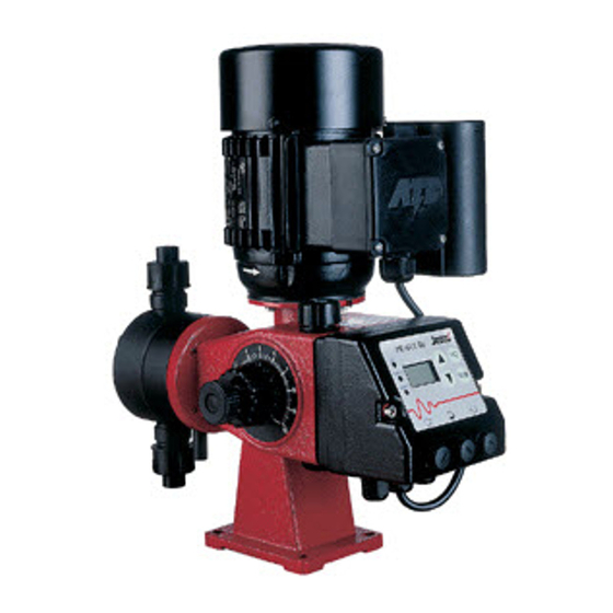
Motor-driven diaphragm dosing pump
Hide thumbs
1
Table Of Contents
2
3
4
5
6
7
8
9
10
11
12
13
14
15
16
17
18
19
20
21
22
23
24
25
26
27
28
29
30
31
32
33
34
35
36
37
38
39
40
41
42
43
44
45
46
47
48
49
50
51
52
page
of
52
Go
/
52
Contents
Table of Contents
Troubleshooting
Bookmarks
Table of Contents
Table of Contents
1 General and Safety Instructions
2 General
Proper Use
Structure of the Dosing Pump
3 Function
4 Dimensional Drawings
5 Technical Data
Electric Motor Data
Technical Data ATE Servomotor MEMDOS E (Optional)
6 Performance Curves
7 Installation
General Information
Installation Location
Drain Pipe
Electrical Connection of the Pump
Wiring Diagrams for ATE Servomotor for Stroke Length Adjustment
Level Control
Back-Pressure and Safety Valves
Injection Nozzle Installation
Installation Example
8 Operation
Stroke Length Adjustment
MEMDOS DX Operating Elements
Switching On/Off
Operating Mode Selection
Alarm
Other Settings
Factory Setting
Connections and Cable Assignments
9 Start-Up
Start-Up of MEMDOS E with ATE Servomotor
10 Shutdown
Disposal of Old Equipment
Device Revision
11 Maintenance
Lubrication
Maintenance of the Bearings
Maintenance of the ATE Servomotor (Optional)
Diaphragm Replacement
Valves
12 Explosion-Proof Dosing Pumps (ATEX)
General
Special Conditions
Dosing of Flammable Media
13 Troubleshooting
14 Spare Parts
15 External Vent (Optional)
Index
Warranty Claim
CE Declaration of Conformity
Advertisement
Quick Links
1
Stroke Length Adjustment
2
Alarm
3
Lubrication
4
Troubleshooting
Download this manual
MEMDOS E/DX
Motor-driven Diaphragm Dosing Pump
Operation manual
EN
02
Read this operation manual before start-up!
To be retained for future reference.
Dosing
Liquids
Gases
Conveying
Systems
Control
Table of
Contents
Previous
Page
Next
Page
1
2
3
4
5
Advertisement
Table of Contents
Need help?
Do you have a question about the MEMDOS E and is the answer not in the manual?
Ask a question
Questions and answers
Related Manuals for Jesco MEMDOS E
Water Pump Jesco MAGDOS LK Operating Instructions Manual
Stepper motor-driven diaphragm dosing pump (60 pages)
Water Pump Jesco MAGDOS E Manual
(67 pages)
Water Pump Jesco MAGDOS DE/DX Operating Manual
Solenoid-diaphragm dosing pump (40 pages)
Water Pump jesco MIDIDOS E Operation & Maintenance Instructions Manual
(36 pages)
Water Pump Jesco MIDIDOS E Series Operation & Maintenance Instructions Manual
Diaphragm dosing pump (36 pages)
Water Pump Jesco MEMDOS DX Operation Manual
Motor-driven diaphragm dosing pump (52 pages)
Water Pump Jesco MAGDOS LB Installation, Operation & Maintenance Instructions Manual
Solenoid-driven diaphragm dosing pump (28 pages)
Water Pump Jesco MAGDOS LT Operation & Maintenance Instructions Manual
(52 pages)
Water Pump Jesco MAGDOS 20-100 Operation & Maintenance Instructions Manual
(22 pages)
Water Pump Jesco C7520 Manual
Pressure chlorine changeover unit (11 pages)
Water Pump Jesco FEDOS E 5 Operating Manual
Piston dosing pump (48 pages)
Water Pump Jesco SD 5 00 01/1 Quick Start Manual
Replacing mechanical seals (2 pages)
Water Pump Jesco 43-20406 Operation & Maintenance Instructions Manual
(8 pages)
Water Pump Jesco EASYDOS Peristaltic V Operating & Maintenance Instruction
(20 pages)
Water Pump Jesco Peristaltic Pump 2.8 l/h Operation & Maintenance Instructions Manual
(28 pages)
This manual is also suitable for:
Memdos dx
Table of Contents
Print
Rename the bookmark
Delete bookmark?
Delete from my manuals?
Login
Sign In
OR
Sign in with Facebook
Sign in with Google
Upload manual
Upload from disk
Upload from URL


Need help?
Do you have a question about the MEMDOS E and is the answer not in the manual?
Questions and answers