
Related Manuals for Jesco MAGDOS DE/DX


Summary of Contents for Jesco MAGDOS DE/DX
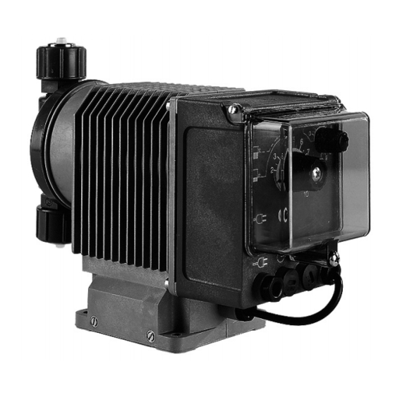
- Page 1 MAGDOS DE/DX Solenoid-diaphragm dosing pump Operating Manual Read this operating manual before start-up! To be retained for future reference.
-
Page 2: Table Of Contents
11.3 Valves ................................26 11.4 Correcting stroke length adjustment ....................... 29 12. Spare parts ................................30 12.1 Spare parts list MAGDOS DE/DX 01...03 ......................31 12.2 Spare parts list MAGDOS DE/DX 07...12 ......................32 12.3 Spare parts list MAGDOS DE/DX 20 ........................ 33 12.4 Spare parts list MAGDOS DE/DX 40...100 ....................... -
Page 3: Safety Instructions
1. Safety instructions 1.1 General This operating manual contains basic instructions to be followed during installation, operation and main- tenance. It is therefore essential that the Operating Manual be read by the installation technician before installing and commissioning the pump/system, as well as by the relevant operating personnel/operating company of the unit. - Page 4 WARNING! To reduce the risk of injury, do not permit children to use this product unless they are closely supervised at all times. WARNING! Risk of electric shock. Connect the device only to a socket outlet with earthing contact protected by a ground fault circuit interrupter (GFCI).
- Page 5 1.9 Unauthorised modification and production of spare parts The device may only be modified or converted in consultation with the manufacturer. Use only the manufac- turer's spare parts and accessories. Otherwise the warranty is invalidated. 1.10 Inadmissible operating practices Any methods of operation other than those described in Section 2 "Proper use" are not permitted and will invalidate any manufacturer liability under the warranty.
- Page 6 Compare the delivery content with the delivery note immediately. If there are any discrepancies, determine the cause. The following are part of the scope of delivery: • Dosing pump MAGDOS DE/DX • Suction and discharge side connections •...
-
Page 7: Use For Intended Purpose
Dosing pumps are used to add chemicals in precisely metered quantities in various processes. Its universal control system allows flexible use of MAGDOS DE/DX in all applications. The dosing rates range from 0.1 to 115 litres per hour. The precise metered quantities at different backpressures can be derived from Section 6 "Delivery Characteristic Curves". -
Page 8: Dimensioned Drawings
4. Dimensioned drawings 4.1 MAGDOS DE/DX 01...12 Ø6 Connection Nominal Type Size diameter DN 4 * 4/6 13 Hose clip 6/12 23 DN 6 6/9 34 *) Only use on the intake side on DE/DX 12, all dimensions in mm 4.2 MAGDOS DE/DX 20...100... -
Page 9: Technical Data
5. Technical data MAGDOS DE/DX 01...100 Unit Delivery rate at max. pressure * 0.1 0.46 0.72 1.86 3.9 12 20.2 50.4 115 Max. delivery pressure * max. stroke frequency Suction head for non-gassing media water col. Max. supply pressure mbar 700 400 200 (∑... -
Page 10: Delivery Characteristic Curves
6. Delivery characteristic curves The delivery characteristic curves refer to water at 20 °C (68 °F). The delivery capacity depends on the medium (density and viscosity) and temperature. Dosing pumps must therefore be gauged in litres for the application. 4 bar 10 bar 6 bar 2 bar... -
Page 11: Installation
NOTE! The size of the lines used in connection with MAGDOS DE/DX 12 must be at least DN 6. DN 4 should only be used for short lines (up to 1 m) and low-viscosity media (<20 mPa s) . -
Page 12: Water Meter Installation
NOTE! The dosing pump must be plugged into a grounded power outlet. The 230 V version of the MAGDOS DE/DX is connected by a shockproof earthing-pin plug. The 115 V version is equipped with a UL/CSA connector. -
Page 13: Pressure Control And Pressure Relief Valves
7.6 Pressure control and pressure relief valves Pressure control valves are used to optimise the dosing process. They are used • to increase the dosing accuracy in the case of fluctuating backpressure. • when the dosing lines are long, in order to prevent excess delivery, since the accelerated medium continues moving due to its own inertia even after the delivery stroke has ended. -
Page 14: Installation Examples
① ⑩ ⑨ On wall bracket ⑤ ① ① MAGDOS DE/DX ② Chemical tank ③ Suction line with integrated low level indica- tion ④ Priming aid This equipment allows easy start-up of small dosing pumps in particular. The air cushion serves as a pulsation damper. - Page 15 4x setscrew ② ② ① Installation example ⑦ ⑧ ⑨ ① MAGDOS DE/DX ② Chemical tank ③ Suction line with integrated low level indication ④ Priming aid ⑤ Electrical agitator ⑥ Pulsation damper ⑦ Injection nozzle with non-return and shutoff valve ⑧...
-
Page 16: Operation
⑪ Selector switch for external actuation (only on MAGDOS DX) ① ② ③ ④ 8.1 Connections and cable assignments Control unit MAGDOS DE/DX Standard version CSA version ① L Voltage supply (2 m cable) BR (brown) BK (black) 230 V AC, 50/60 Hz... -
Page 17: Flow Rate Setting
3 = ground (GND) BU (blue) Cable WH (white) = Pulses (MAGDOS DE/DX 01 ... 12) BN (brown) = Ground (GND) NOTE! The protection class of the control unit is only ensured if the connection ports are protected by caps or the standard connectors are inserted. - Page 18 8.2.1 Operating mode selection MAGDOS DE The rotary switch ⑥ defines the stroke rate (0..100/min) infinitely variable in internal mode. External mode is activated by turning to the left-hand stop (beyond the detent). A dosing stroke is executed for every incoming pulse in external mode. IMPORTANT! Pulses are not saved when the dosing pump is driven at more than the maximum pulse rate (see Technical Data).
-
Page 19: Start-Up
9. Start-up CAUTION! Personal protective equipment as specified by the applicable accident prevention regulations must be worn during all work on the dosing pump/system! Protective clothing Protective gloves Protective goggles 1. For initial start-up, set the pump to internal operation at 100% stroke frequency and allow the pump to prime. -
Page 20: Automatic Venting
9.1.1 Automatic venting ② ④ ③ ① ⑤ The automatic venting facility (standard features on DE/DX 03, 07 otherwise optional extra) consists of a non-return ball valve. The ball ③ rolls against the seat during the suction stroke and away from it during the pressure stroke. -
Page 21: Shutdown
10. Shutdown Before starting any maintenance work or before long downtimes, drain the chemicals from the dosing pump and rinse it thoroughly with a neutral medium. CAUTION! Excess chemicals must be disposed of properly. Observe the applicable accident prevention regulations and wear personal protective equipment. -
Page 22: Maintenance
It may be necessary to readjust the dosing pump after replacing the diaphragm or other spare parts (Section 11.5 Correcting stroke length adjustment). 11.1 Replacing diaphragm, MAGDOS DE/DX 01...12 CAUTION! Chemical may spray out. This may lead to chemical or other burns. The dosing pump must always be depressurised and rinsed with water or a suitable medium before starting any work on the dosing pump. - Page 23 NOTE! Check that the deflector plate ⑤ is in perfect condition (Section 11.2 "Checking and replacing deflector"). 5. Grease the diaphragm rod with Molykote Longterm W2 at the contact point with the housing and along the diaphragm thread. 6. Push the support plate on to the threaded connector of the new diaphragm with the concave side facing towards the diaphragm (see Fig.
- Page 24 11.1.1 Replacing diaphragm, MAGDOS DE/DX 20...100 ① Dosing head with valves ② Diaphragm ③ Support plate (only on DE/DX 20) ④ Deflector plate ⑤ Diaphragm flange ⑥ Diaphragm rod ⑦ Compression spring ⑧ ⑧ Drive unit ⑦ ⑥ ⑤ ④...
- Page 25 10. Attach dosing head ①. Tighten screws crosswise, e.g. top left – bottom right – top right – bottom left. The tightening torque for the dosing head screws is 2 Nm on the MAGDOS DE/DX 20 and 6 Nm on the MAGDOS DE/DX 40…100 (see Fig.
-
Page 26: Checking And Replacing Deflector Plate
Repeat steps 1 - 4 in Section 11.1 "Replacing diaphragm". The deflector plate ⑤ on the MAGDOS DE/DX 01...12 is accessible after removing diaphragm insert ④. The diaphragm insert can be removed... - Page 27 Double ball valves DN 3 Valves DN 4 MAGDOS DE/DX 01 ... 03 MAGDOS DE/DX 07 ... 12 Double-ball valves Spring-loaded valves Discharge valve ⑨ ⑨ ⑨ ⑧ ⑧ ⑧ ③ ③ ③ ④ ④ ⑤ ⑤ ④ ⑥ ⑥...
- Page 28 Valves DN 6 Valves DN 10 MAGDOS DE/DX 20 MAGDOS DE/DX 40 ... 100 Double-ball valves Spring-loaded valves Double-ball valves Spring-loaded valves Discharge valve ⑦ ⑦ ① ① ④ ④ ③ ③ ⑤ ⑧ ② ⑥ ⑤ ② ④ ③...
-
Page 29: Correcting Stroke Length Adjustment
11.4 Correcting stroke length adjustment IMPORTANT! It may be necessary to readjust the dosing pump after replacing the diaphragm or other spare parts ① ② ① Stroke length adjustment knob, ② lock screw Dosing pump set to internal control. Regardless of the pointer position, release the lock screw and turn the stroke length adjustment knob counterclockwise until the dosing pump stops delivering medium or delivery is reduced to a minimum during depressurised operation. -
Page 30: Spare Parts
12. Spare parts MAGDOS DE/DX 81683 81424 81424 81463 81464 81465 81466 81467 ⑧ Diaphragm 29312 23892 28977 ⑨ Support plate Spacer 33897 22066 22066 22056 22057 22058 ⑩ Deflector plate 230 V AC 32956 32732 32719 32733 32720 32722 32723 34338 34339 34340 ⑪... -
Page 31: Spare Parts List Magdos De/Dx 01
⑩ ⑪ ⑥ ⑫ Fig. 12.1: Spare parts MAGDOS DE/DX 01 ... 03 Maintenance kits for DE/DX 01...03 with double ball valves ⑥ Double ball valves Consisting of ① flat gaskets, ② balls, ④ valve seats, ⑤ O- rings and ⑧ diaphragm... -
Page 32: Spare Parts List Magdos De/Dx 07
⑤ ⑤ ⑤ ⑤ ⑥ ⑦ ⑧ ⑨ ⑩ ⑪ ⑫ Fig. 12.2: Spare parts MAGDOS DE/DX 07 ... 12 Maintenance kits DE/DX 07...12 with double ball valves with spring-loaded valves Consisting of: MAGDOS DE/DX 07...4 07...4 ① Seals PVC / Ceramic / FPM... -
Page 33: Spare Parts List Magdos De/Dx 20
12.3 Spare parts list MAGDOS DE/DX 20 ① ① ① ① ② ④ ① ③ ② ② ④ ④ ① ① ⑫ ⑤ ⑥ ⑦ ⑧ ⑨ ⑩ ⑪ Fig. 12.3: Spare parts MAGDOS DE/DX 20 Maintenance kits with double ball valves... -
Page 34: Spare Parts List Magdos De/Dx 40
① ① ① ⑪ ⑥ ⑦ ⑩ ⑫ ⑤ ⑧ Fig. 12.4: Spare parts MAGDOS DE/DX 40 ... 100 Maintenance kits with double ball valves with spring-loaded DE/DX 40 ... 100 valves Consisting of: MAGDOS DE/DX ① Seals PP / Ceramic / FPM... -
Page 35: Troubleshooting
13. Troubleshooting Problem Possible cause Remedy Dosing pump Valves leaking or blocked. Clean the valves and vent the dosing not delivering pump. or output too See also "Start-up" low. Valves incorrectly installed. Reassemble the valves. Ensure that the valve balls are located above the valve seats. -
Page 36: Index
Index Replacing the diaphragm ..........22 Checking and replacing deflector plate ......26 Shutdown ..............21 Declaration of conformity ..........39 Start-up................19 Declaration of no objection ..........37 Stroke length adjustment ..........29 Delivery characteristic curves ........10 System design ..............11 Delivery Rate ..............19 Diaphragm replacement ..........22 Digital display ...............18 Technical data ..............9 Dosing accuracy ............11... -
Page 37: Declaration Of No Objection
Declaration of No Objection When sending in for repair, please copy this form, fill in and send along with each device! Declaration of No Objection - Form (please fill in one form for each device and attach it to the outside of the device) We are returning the following device for repair: Device and device type: ...................... -
Page 38: Warranty Claim
Warranty claim Please copy and enclose with the device! If the device fails during the warranty period, please clean it and return, accompanied by the completed warranty claim form. Sender Company: ................. Telephone: ........Date: ........Address: ....................................Contact person: ................................... Manufacturer order No.: ............ -
Page 39: Ec Declaration Of Conformity
(NL) EU-overeenstemmingsverklaring Ondergetekende Lutz-Jesco GmbH, bevestigt, dat het volgende genoemde apparaat in de door ons in de handel gebrachte uitvoering voldoet aan de eis van, en in overeenstemming is met de EU-richtlijnen, de EU-veiligheidsstandaard en de voor het product specifieke standaard. Bij een niet met ons afgestemde verandering aan het apparaat verliest deze verklaring haar geldigheid. - Page 40 Order No. BA-10220-02-V06 Subject to technical changes and inaccuracies © Lutz-Jesco GmbH 06.2018...
Need help?
Do you have a question about the MAGDOS DE/DX and is the answer not in the manual?
Questions and answers