Table of Contents
Advertisement
Quick Links
SAFETY PRECAUTION FOR SERVICE MANUAL ............................................................................................................ 2
IMPORTANT SERVICE NOTES (FOR U.K. ONLY ) ......................................................................................................... 2
SPECIFICATIONS ............................................................................................................................................................. 3
NAMES OF PARTS ........................................................................................................................................................... 4
OPERATION MANUAL ...................................................................................................................................................... 6
DISASSEMBLY .................................................................................................................................................................. 7
REMOVING AND REINSTALLING THE MAIN PARTS ..................................................................................................... 9
ADJUSTMENT ................................................................................................................................................................. 10
NOTES ON SCHEMATIC DIAGRAM .............................................................................................................................. 12
TYPE OF TRANSISTOR AND LED ................................................................................................................................. 12
BLOCK DIAGRAM ........................................................................................................................................................... 13
SCHEMATIC DIAGRAM / WIRING SIDE OF P.W.BOARD .............................................................................................. 16
WAVEFORMS OF CD CIRCUIT ...................................................................................................................................... 31
TROUBLESHOOTING ..................................................................................................................................................... 32
FUNCTION TABLE OF IC ................................................................................................................................................ 36
FL SEGMENT ................................................................................................................................................................... 41
PARTS GUIDE/EXPLODED VIEW
All manuals and user guides at all-guides.com
SERVICE MANUAL
1
CONTENTS
SHARP CORPORATION
- 1 -
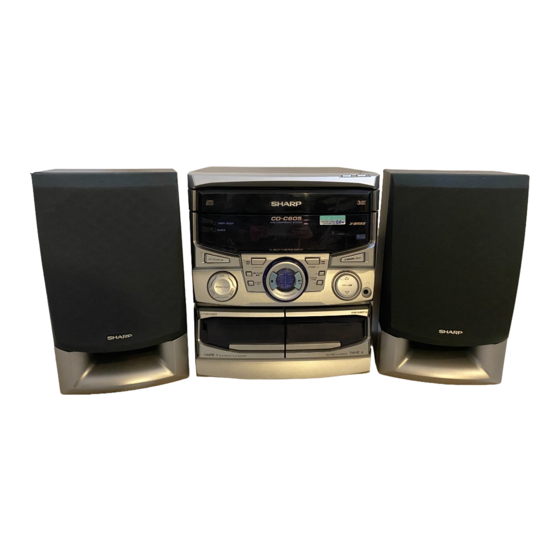
CD-C605H
CD-C605H mini component system consisting of
CD-C605H (Main unit), CP-C605H (Speaker system).
• In the interests of user-safety the set should be restored to its
original condition and only parts identical to those specified be
used.
• Note for users in U.K.
Recording and playback of any material may require consent
which SHARP is unable to give. Please refer particularly to the
provisions of Copyright Act 1956, the Dramatic and Musical
Prefomers Protection Act 1956, the Preformers Protection Acts
1963 and 1972 and to any subsequent statutory enactments and
orders.
This document has been published to be used
for after sales service only.
The contents are subject to change without notice.
CD-C605H
No. S5927CDC605H/
Page
Advertisement
Table of Contents

Related Manuals for Sharp CD-C605H


Summary of Contents for Sharp CD-C605H
-
Page 1: Table Of Contents
• Note for users in U.K. Recording and playback of any material may require consent which SHARP is unable to give. Please refer particularly to the provisions of Copyright Act 1956, the Dramatic and Musical Prefomers Protection Act 1956, the Preformers Protection Acts 1963 and 1972 and to any subsequent statutory enactments and orders. -
Page 2: Safety Precaution For Service Manual
All manuals and user guides at all-guides.com CD-C605H SAFETY PRECAUTION FOR SERVICE MANUAL Precaution to be taken when replacing and servicing the Laser Pickup. Laser Diode Properties Material: GaAIAs Wavelength: 780 nm The AEL (Accessible Emission Level) of Laser Power Output Emission Duration: continuous Laser Output: max. -
Page 3: Specifications
All manuals and user guides at all-guides.com CD-C605H FOR A COMPLETE DESCRIPTION OF THE OPERATION OF THIS UNIT, PLEASE REFER TO THE OPERATION MANUAL. SPECIFICATIONS CD-C605H Cassette deck section General Frequency response: 50 - 14,000 Hz (Normal tape) Power source:... -
Page 4: Names Of Parts
All manuals and user guides at all-guides.com CD-C605H NAMES OF PARTS CD-C605H Front panel 1. Disc Tray 2. Disc Skip Button 3. Open/Close Button 4. (CD) Disc Number Indicator 5. (TAPE 2) Record Indicator 6. Sleep Indicator 7. Extra Bass Indicator 8. - Page 5 All manuals and user guides at all-guides.com CD-C605H Rear panel 1. Speaker Terminals 2. AC Power Input Socket 3. FM 75 Ohms Aerial Socket 4. AM Loop Aerial Input Socket CP-C605H Speaker 1. Full-Range Speaker 2. Bass Reflex Duct 3. Speaker Wire...
-
Page 6: Operation Manual
All manuals and user guides at all-guides.com CD-C605H OPERATION MANUAL – 6 –... -
Page 7: Disassembly
All manuals and user guides at all-guides.com CD-C605H DISASSEMBLY CD-C605H Caution on Disassembly Follow the below-mentioned notes when disassembling (A1)x2 Top Cabinet the unit and reassembling it, to keep it safe and ensure ø3 x12mm excellent performance: Front Panel 1. Take cassette tape and compact disc out of the unit. - Page 8 All manuals and user guides at all-guides.com CD-C605H (E1)x3 (N1) x1 ø3x8mm ø3x10mm Front Panel CD Servo PWB (N2) x2 Main PWB (E2)x1 Main Tuner PWB (E3)x2 (N2) x2 (E2)x1 CD Player Unit (F1)x2 (E3)x1 ø3x8mm Tuner PWB (G1)x2 Figure 8-4 (E2)x3 ø3x8mm...
-
Page 9: Removing And Reinstalling The Main Parts
All manuals and user guides at all-guides.com CD-C605H CP-C605H PROCEDURE STEP REMOVAL FIGURE Speaker 1. Net Frame ....(A1) x1 2. Duct Panel ....(A2) x1 3. Screw ...... (A3) x4 Speaker Box (A3)x4 (A1)x1 ø4x12mm Net Frame (A2)x1 Duct Panle... -
Page 10: Adjustment
All manuals and user guides at all-guides.com CD-C605H ADJUSTMENT MECHANISM SECTION TUNER SECTION • Driving Force Check fL: Low-range frequency fH: High-renge frequency Torque Meter Specified Value • AM IF/RF Play: TW-2412 Tape 1: Over 80 g Signal generator: 400 Hz, 30%, AM modulated... - Page 11 All manuals and user guides at all-guides.com CD-C605H TEST MODE • Setting the test mode Any one of test mode can be set by pressing several keys as follows. <REC. PAUSE> + <DISC. SKIP> + <POWER> TEST: CD operation test •...
-
Page 12: Notes On Schematic Diagram
All manuals and user guides at all-guides.com CD-C605H NOTES ON SCHEMATIC DIAGRAM • Resistor: • The indicated voltage in each section is the one measured To differentiate the units of resistors, such symbol as K and by Digital Multimeter between such a section and the chas- M are used: the symbol K means 1000 ohm and the symbol sis with no signal given. -
Page 13: Block Diagram
All manuals and user guides at all-guides.com CD-C605H TO DISPLAY TO MAIN PWB (TO IC401) 1 2 3 4 5 6 CNP11 – 9 8 7 6 5 4 3 2 1 CNS10 9 8 7 6 5 4 3 2 1... - Page 14 All manuals and user guides at all-guides.com CD-C605H FOOL PROO SO301 FM ANTENNA FM IF TERMINAL F.A. FM IF FM IF FE301 SOLM CF301 CF302 Q301 SOLENO AM IF AM IF FM FRONT END CF352 T351 FM IF IN AM LOOP...
- Page 15 All manuals and user guides at all-guides.com CD-C605H SWM3 FOOL PROOF SWM4 FL701 F.A.S MOTOR FL DISPLAY SOLM1 DRIVER SOLENOID Q701 SWM5 14 17 18 21 30 32 33 Q702 FL SEGMENT DRIVER SOLENOID TAPE MOTOR DRIVER Q703 IC701 IX0300AW...
-
Page 16: Schematic Diagram / Wiring Side Of P.w.board
All manuals and user guides at all-guides.com CD-C605H FL701 FL DISPLAY Q703 KRC107 M FL SEGMENT DRIVER 3 -25V 4.8V R791 -25V R741 100K -24.8V R735 -24.8V R736 -24.8V C703 R737 1/50 -27.8V R738 AVDD -18.2V A/D KEYIN 1 -18.2V AVREF -21.2V... - Page 17 All manuals and user guides at all-guides.com CD-C605H R758 1.8K SWITCH PWB-A4 R761 R762 R778 R780 FW705 1.2K 8.2K 3.9K SW708 SW701 SW702 SW703 SW707 DISC OPEN/ SKIP CLOSE TIMER/ CLOCK STANDBY SLEEP R763 R765 R767 R770 R773 R776 1.2K 1.5K...
- Page 18 All manuals and user guides at all-guides.com CD-C605H IC601 LA4282 FM SIGNAL POWER AMP. C609 470/25 C631 0.022 (ML) C634 0.022 C601 C611 R601 (ML) 10/16 (ML) C605 R603 100/25 C612 C613 C602 R604 C604 (ML) 10/16 (ML) 0.29µ 470P...
- Page 19 All manuals and user guides at all-guides.com CD-C605H C636 0.001 D631 DS1SS133 D632 DS1SS133 HEADPHONES PWB-A3 JK601 FW601 HEADPHONES R614 R613 C641 L902 0.001 2.2mH C642 0.001 C661 L651 L652 0.001 0.29µH 0.29µH L-CH When Servicing pay, SO601 attention as the area...
- Page 20 All manuals and user guides at all-guides.com CD-C605H R452 AUDIO R-CH PROCESSOR A_GND L-CH R451 IC401 CD_GND C406 M62439SP 4.7/50 C418 4 +12V R416 1.5K R422 1.5K R415 1.5K R414 R421 1.5K CNS401 BI401 1.5K R420 1.5K C407 C411(ML) 4.7/50 0.033...
- Page 21 All manuals and user guides at all-guides.com CD-C605H FM SIGNAL CD SIGNAL PLAYBACK SIGNAL RECORD SIGNAL C418 4.7/50 1.5K 1.5K 1.5K C454 470P C415 0.033(ML) C416 0.22 R426 ZD402 2.2K DZ2.4BSB C424 0.22 R425 C422 10/50 C460 0.001 D_GND A_+12V...
- Page 22 All manuals and user guides at all-guides.com CD-C605H TUNER PWB-F AM SIGNAL FM SIGNAL C331 C342 C330 R358 0.047 0.022 8.2K (CH) VR351 C323 T302 C332 10K(B) 0.022 0.022 L353 AM ANT. FM MUTE LEVEL C338 0.001 5.1V D301 DS1SS133 3.6V...
- Page 23 All manuals and user guides at all-guides.com CD-C605H TP302 C373 0.015 C371 R361 1/50 1.2K L354 LOW PASS MUTING FILTER Q353 R362 R350 C372 KTC3199 GR 1.2K 2.7K 1/50 C367 R365 1/50 R367 C375 3.3/50 R368 R366 AM IF IN...
- Page 24 All manuals and user guides at all-guides.com CD-C605H 0.01 47/16 1/50 0.33/50 0.01 2SA1318 LASER DRIVER 64 63 61 60 55 54 53 52 51 50 49 VCC1 CNS1B CNS1A – + 2.5V FIN2 – + 2.5V FIN1 EFBAL 2.5V –...
- Page 25 All manuals and user guides at all-guides.com CD-C605H CD SERVO PWB-B CD SIGNAL 100P (CH) 0.01 64 63 60 59 58 57 56 55 54 53 52 51 50 2.3V EFLG µ-COM SBSY SUB-CODE INTERFACE 0.1V DEF1 XVSS 16.93MHz 2.1V...
- Page 26 All manuals and user guides at all-guides.com CD-C605H HEADPHONES PWB-A3 MAIN PWB-A1 JK601 HEADPHONES PT902 D923 BACK UP TRANSFORMER D924 C927 C928 D921 D920 D922 C925 When Servicing pay, attention as the area D918 C633 IC601 enclosed by this IC902...
- Page 27 All manuals and user guides at all-guides.com CD-C605H SWITCH PWB-A4 TO CD SERVO PWB SW708 SW707 P28 5-G OPEN/ DISC CLOSE SKIP CNP12 R780 CNS701 15 14 13 12 11 10 9 8 7 6 5 4 3 2 1...
- Page 28 All manuals and user guides at all-guides.com CD-C605H CD MOTOR PWB-C SOLM2 SLED MOTOR SOLENOID TRAY MOTOR SPINDLE MOTOR PWB-D PICKUP IN CNS3A CNS3B DISC NUMBER TURNTABLE UP/ DOWN/LOADING PICKUP UNIT MOTOR OPEN/CLOSE BIM5 CNS1A CNS1B CNS5 MECHA UP CNS2A...
- Page 29 All manuals and user guides at all-guides.com CD-C605H AM LOOP SO301 ANTENNA FM ANTENNA 75 Ohms TERMINAL C301 CNP301 C338 X352 C394 D302 L341 D301 C381 C397 C382 C321 T302 Q301 R378 C347 C330 C341 R398 C331 C332 C337 C384...
- Page 30 All manuals and user guides at all-guides.com CD-C605H TAPE MECHANISM ASSEMBLY TAPE MECHANISM PWB-E FROM SWM3 DISPLAY FOOL PROOF(220-8) CNS702 FWM2 P26 8-F CNPM1 FWM1 CNPM2 PHM1 SOLENOID SOLM1 SWM4 F. A. S (220-9) TAPE MOTOR(220-1) SWM5 (220-10) TAPE 1...
-
Page 31: Waveforms Of Cd Circuit
All manuals and user guides at all-guides.com CD-C605H WAVEFORMS OF CD CIRCUIT STOP PLAY FOCUS SERCH 0.5ms 10.0 V IC1 33 JP+ 0.50 V 0.5ms IC1 20 FE 10.0 V IC1 32 JP- 0.5ms 0.50 V IC1 14 JP 0.5ms 5.0 V... -
Page 32: Troubleshooting
All manuals and user guides at all-guides.com CD-C605H TROUBLESHOOTING When the CD does not function When the CD section does not operate when the objective lens of the optical pickup is dirty, this section may not operate. Clean the objective lens, and check the playback operation. When this section does not operate even after the above step is taken, check the following items. - Page 33 All manuals and user guides at all-guides.com CD-C605H • When turntable fails to move. Is there following voltage input on the IC701 pin 41 in the Check the MECHA UP switch and the wiring from the IC701 pin 41 to the MECHA UP switch.
- Page 34 All manuals and user guides at all-guides.com CD-C605H • The CD operating keys work. Check the Focus - HF system. Playback can be performed without a disc. Does the pick-up move up and down twice? Focus search OK Does the output waveform of IC1(16)(FD) match that shown in Check the area around IC3-CNP2.
- Page 35 All manuals and user guides at all-guides.com CD-C605H • Check the tracking system. Check waveform of IC1 pin 7 (TE). Check the periphery of IC 1 The waveform shown in Fig. Tracking servo is pin 8 to pin 15, and IC 5 to 35-1 appears, and no-disc inoperative.
-
Page 36: Function Table Of Ic
All manuals and user guides at all-guides.com CD-C605H FUNCTION TABLE OF IC IC1 VHiLA9241M/-1: Servo Amp. (LA9241M) (1/2) Pin No. Port Name Function FIN2 Connection pin for photodiode of pickup. RF signal is generated through addition with FIN pin, and FE signal is generated through subtraction. - Page 37 All manuals and user guides at all-guides.com CD-C605H IC1 VHiLA9241M/-1: Servo Amp. (LA9241M) (2/2) Pin No. Port Name Function Defect detection output pin of disc. Reference clock input pin. 4.23MHz of DSP is input. Microcomputer command clock input pin. Microcomputer command data input pin.
- Page 38 All manuals and user guides at all-guides.com CD-C605H IC2 VHiLC78622N-1: Servo/Signal Control (LC78622N) (1/2) Terminal Name Input/Output Function Pin No. DEF1 Input Input terminal of defect detection signal (DEF). (Connected to OV when not used.) Input For PLL Input terminal for test. Pull-down resistor is integrated. Surely connected to 0V.
- Page 39 All manuals and user guides at all-guides.com CD-C605H IC2 VHiLC78622N-1: Servo/Signal Control (LC78622N) (2/2) Pin No. Terminal Name Input/Output Function SFSY (NC) Output Output terminal of synchronous signal of subcode frame. It drops when subcode stands by. SBCK Input Clock input terminal to read subcode. Schmit input (Connected to 0V when not used.)
- Page 40 All manuals and user guides at all-guides.com CD-C605H IC701 RH-iX0300AWZZ: System Microcomputer (IX0300AW) (2/2) Pin No. Port Name Terminal Name Input/Output Function P04/XT1 — NC (Non Connect) — NC (Non Connect) — Ground voltage — — Main clock — —...
-
Page 41: Fl Segment
All manuals and user guides at all-guides.com CD-C605H FL701 VVKSVA9MS13-1 : FL Display h j k ( 1G~8G ) PIN CONNECTION Pin No. CONNECTION Pin No. CONNECTION Figure 41 FL SEGMENT – 41 –... - Page 42 All manuals and user guides at all-guides.com CD-C605H — M E M O — – 42 –...
- Page 43 “HOW TO ORDER REPLACEMENT PARTS” To have your order filled promptly and correctly, please furnish the For U.S.A. only following information. Contact your nearest SHARP Parts Distributor to order. 1. MODEL NUMBER 2. REF. No. 3. PART NO. 4. DESCRIPTION For location of SHARP Parts Distributor, Please call Toll-Free;...
- Page 44 All manuals and user guides at all-guides.com CD-C605H PRICE PRICE PARTS CODE DESCRIPTION PARTS CODE DESCRIPTION RANK RANK FILTERS CD-C605H CF301,302 RFILF0072AFZZ AG FM IF INTEGRATED CIRCUITS CF351 RFILF0003AWZZ AK FM IF CF352 RFILA0009AWZZ AE AM IF VHILA9241M/-1 AS Servo Amp.,LA9241M...
- Page 45 All manuals and user guides at all-guides.com CD-C605H PRICE PRICE DESCRIPTION PARTS CODE DESCRIPTION PARTS CODE RANK RANK AA 0.022 µF,25V AB 0.047 µF,50V VCKYTV1EF223Z C505 VCKYPA1HF473Z AC 100 µF,16V,Electrolytic AA 0.001 µF,50V C51,52 VCEAZA1CW107M J C506,507 VCKYMN1HB102K J AA 0.001 µF,50V AC 100 µF,16V,Electrolytic...
- Page 46 All manuals and user guides at all-guides.com CD-C605H PRICE PRICE PARTS CODE DESCRIPTION PARTS CODE DESCRIPTION RANK RANK RESISTORS R358 VRD-MN2BD822J AA 8.2 kohms,1/8W R359 VRD-MN2BD182J AA 1.8 kohms,1/8W R360 VRD-MN2BD472J AA 4.7 kohms,1/8W VRD-MN2BD000C AA 0 ohm,Jumper,ø1.4×3.5mm,Ivory R361,362 VRD-MN2BD122J AA 1.2 kohms,1/8W...
- Page 47 All manuals and user guides at all-guides.com CD-C605H PRICE PRICE DESCRIPTION PARTS CODE DESCRIPTION PARTS CODE RANK RANK OTHER CIRCUITRY PARTS R556 VRD-MN2BD472J AA 4.7 kohms,1/8W R557 VRD-MN2BD120J AA 12 ohms,1/8W R561 VRD-ST2CD223J AA 22 kohms,1/6W BI401/CNS401 QCNWN1380AWZZ J AF Connector Ass’y,6/6Pin...
- Page 48 All manuals and user guides at all-guides.com CD-C605H PRICE PRICE PARTS CODE DESCRIPTION PARTS CODE DESCRIPTION RANK RANK CD MECHANISM PARTS 220- 9(SWM4) QSW-F9003AWZZ AG Switch,Leaf Type [F.A.S.] 220-10(SWM5) 92LM-SW1658A AB Switch,Leaf Type [CAM] 92LN-BAND1318A AA Nylon Band,80mm NGERH0011AWZZ J...
- Page 49 All manuals and user guides at all-guides.com CD-C605H PRICE PRICE DESCRIPTION PARTS CODE DESCRIPTION PARTS CODE RANK RANK 92LF-ANT1535A AF FM Antenna QANTL0008AWZZ AH AM Loop Antenna RRMCG0180AWSA J AR Remote Control GFTAB1022AWSA J Battery Lid,Remote Control TLABZ0571AWZZ AC Label,Feature,Unit,Tape 1...
- Page 50 All manuals and user guides at all-guides.com CD-C605H CD-C605H 306-2 306-1 306-3 703x2 305x2 PWB-C Figure 7 CD MECHANISM EXPLODED VIEW – 7 –...
- Page 51 All manuals and user guides at all-guides.com CD-C605H CD-C605H 610x5 202-1 PWB-A5 PWB-A2 LED701 608x2 PWB-A4 607x2 264x4 609x2 607x5 PWB-A1 202-2 FL701 201-12 264x2 201-10 201-7 201-8 201-6 201-5 608x2 Silicon 609x4 201-13 201-11 grease IC601 201-1 PWB-F 201-3...
- Page 52 All manuals and user guides at all-guides.com CD-C605H CD-C605H 606x2 228-3 228-2 228-1 606x2 204-2 204-4 204-1 204-3 247x2 MECHANISM 602x2 PWB-D 605x4 SOLM2 PWB-B Figure 9 CABINET EXPLODED VIEW (2/2) – 9 –...
- Page 53 All manuals and user guides at all-guides.com CD-C605H CP-C605H SP1(L-CH) SP2(R-CH) 704x4 SP1(L-CH) SP2(R-CH) Figure 10 SPEAKER EXPLODED VIEW – 10 –...
-
Page 54: Packing Method(For U.k. Only )
All manuals and user guides at all-guides.com CD-C605H PACKING METHOD (FOR U.K. ONLY) 8 Operation Manual TiNSE0252AWZZ Setting position of switches and knobs 10 FM Antenna 92LF-ANT1535A Tape Mechanism STOP 11 AM Loop Antenna QANTL0008AWZZ 12 Remote Control RRMCG0180AWSA 13 Label, Feature, Unit, Tape1... - Page 55 All manuals and user guides at all-guides.com CD-C605H — M E M O — – 12 –...
- Page 56 All manuals and user guides at all-guides.com CD-C605H © COPYRIGHT 1999 BY SHARP COPORATION ALL RIGHTS RESERVED. No part of this publication may be reproduced, stored in a retrieval system, or transmitted in any from or by any means, electronic, mechanical, photocopying, recording, or otherwise, without prior written permission of the publisher.
Need help?
Do you have a question about the CD-C605H and is the answer not in the manual?
Questions and answers