Advertisement
Quick Links
EVCO S.p.A. | EV3802 | Instruction sheet ver. 2.0 | Code 1043802E203 | Page 1 of 3 | PT 49/20
EV3802
I
ENGLISH
-
230 VAC or 115 VAC power supply (according to the model)
-
cabinet probe and needle probe (PTC/NTC)
-
door switch/multi-purpose input
-
compressor relay 16 A res. @ 250 VAC
-
alarm buzzer
-
TTL MODBUS slave port for EVconnect app, EPoCA remote monitoring system or for
BMS
-
operation with EV3KEY programming key.
Purchasing code
EV3802N7
EV3802N5
1
MEASUREMENTS AND INSTALLATION
Measurements in mm (inches). To be fitted to a panel, snap-in brackets provided.
INSTALLATION PRECAUTIONS
-
the thickness of the panel must be between 0.8 and 2.0 mm (1/32 and 1/16 in)
-
ensure that the working conditions are within the limits stated in the TECHNICAL
SPECIFICATIONS section
-
do not install the device close to heat sources, equipment with a strong magnetic field,
in places subject to direct sunlight, rain, damp, excessive dust, mechanical vibrations
or shocks
-
in compliance with safety regulations, the device must be installed properly to ensure
adequate protection from contact with electrical parts. All protective parts must be
fixed in such a way as to need the aid of a tool to remove them.
2
ELECTRICAL CONNECTION
N.B.
- use cables of an adequate section for the current running through them
- to reduce any electromagnetic interference, locate the power cables as far away as
possible from the signal cables.
PRECAUTIONS FOR ELECTRICAL CONNECTION
-
if using an electrical or pneumatic screwdriver, adjust the tightening torque
-
if the device is moved from a cold to a warm place, humidity may cause condensation
to form inside. Wait for about an hour before switching on the power
-
make sure that the supply voltage, electrical frequency and power are within the set
limits. See the section TECHNICAL SPECIFICATIONS
-
disconnect the power supply before carrying out any type of maintenance
-
do not use the device as a safety device
-
for repairs and for further information, contact the EVCO sales network.
3
FIRST-TIME USE
1.
Carry out the installation following the instructions given in the section MEASUREMENTS
AND INSTALLATION.
2.
Power up the device as set out in the section ELECTRICAL CONNECTION: an internal
test will start up.
The test normally takes a few seconds; when it is finished the display will switch off.
3.
Configure the device as shown in the section Setting configuration parameters.
Recommended configuration parameters for first-time use:
PAR.
DEF.
PARAMETER
P0
1
type of probe
P2
0
temperature measurement unit
u0
1
auxiliary output configuration
Then check that the remaining settings are appropriate; see the section CONFIGURA-
TION PARAMETERS.
4.
Disconnect the device from the mains.
5.
Make the electrical connection as shown in the section ELECTRICAL CONNECTION,
without powering up the device.
6.
For the connection in an RS-485 network connect the interface EVIF22TSX or
EVIF23TSX, to use the device with the EPoCA remote monitoring system, connect the
EVIF25TWX module, to use the device with the APP EVconnect connect the interface
EVIF25TBX; see the relevant instruction sheets. If EVIF22TSX or EVIF23TSX is
used, set parameter bLE to 0.
7.
Power up the device again.
Basic controllers for blast chillers
4
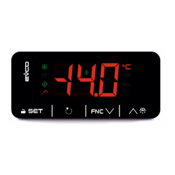
USER INTERFACE AND MAIN FUNCTIONS
4.1
Switching the device on/off
Power up/disconnect the device.
If the device is switched on and no cycle is active, the display will show the cabinet tempera-
Power supply
ture.
230 VAC
If the display shows an alarm code, see the section ALARMS.
115 VAC
If no cycle is active, after 10 s have elapsed without the keys being pressed, the display will
automatically switch off, except for the low consumption LEDs.
When 60 s have elapsed without the keys being pressed, the display will show the "Loc" label
and the keypad will lock automatically.
LED
ON
compressor
on
defrost active
evaporator fans on
temperature controlled
cycle active
conservation active
alarm active
temperature displayed
°C/°F
min
time displayed
time controlled cycle is
selected
4.2
Switching the display back on
Touch a key.
4.3
Unlocking the keypad
Touch a key for 1 s: the display will show the label "UnL".
4.4
Activating an operating cycle
Check that the keypad is not locked and that defrosting is not active.
1.
LAB.
PoS
nEG
PoS
nEG
2.
4.5
Activating the last cycle carried out
Check that the keypad is not locked and that defrosting is not active.
1.
2.
4.6
Interrupting an operating cycle
Check that the keypad is not locked.
1.
4.7
Setting the cabinet setpoint during conservation
Check that the keypad is not locked.
1.
2.
3.
MIN... MAX.
The setting is temporary: when a new cycle is activated (and after a power failure), the device
0 = PTC
1 = NTC
will restore the r9/rA values.
0 = °C
1 = °F
0 = defrosting
4.8
Activating manual defrost
1 = evaporator fans
Check that the keypad is not locked and that blast chilling/freezing is not active.
1.
4.9
Silencing the buzzer
Touch a key.
5
OPERATING CYCLES
5.1
Initial information
Cycles managed:
-
time controlled blast chilling and conservation
-
time controlled blast freezing and conservation
-
temperature controlled blast chilling and conservation
-
temperature controlled blast freezing and conservation.
Before each temperature controlled cycle, a test is run to check that the needle probe is cor-
rectly inserted.
The test consists of two phases: if the first one is completed successfully, the second one is not
carried out.
The first phase is completed successfully if [(needle temperature - cabinet temperature) >
threshold rc] 3 times out of 5, checked every 10 s. The second phase is completed successfully
if [(needle temperature - cabinet temperature) > 1 °C/°F] 6 times out of 8 (compared to previ-
ous test), checked every (duration rd/8) s.
If the test fails, the corresponding time controlled cycle is activated.
5.2
Activating time controlled blast chilling/freezing and conservation
Check that the keypad is not locked and that defrosting is not active.
OFF
FLASHING
switched
compressor
switched
compressor protection in progress
off
-
dripping active
evaporator fans off
evaporator fan delay in progress
-
- temperature controlled cycle se-
lected
- test to check needle probe is
correctly inserted in progress;
when time controlled cycle LED
is on, test has failed and time
controlled cycle is active
- when alarm LED is on, blast
chilling/freezing has failed and
is active
- when alarm LED flashes, blast
chilling/freezing has failed and
conservation is active
-
- setpoint during conservation be-
ing set
-
-
-
-
-
residual time maximum duration
of temperature
chilling/freezing displayed
-
time controlled cycle active
Touch the SET key to select a cycle.
LED
DESCRIPTION
time controlled blast chilling and conservation (if E0 = 0 or 1)
time controlled blast freezing and conservation (if E0 = 1 or 2)
temperature controlled blast chilling and conservation (if E0 = 0
or 1)
temperature controlled blast freezing and conservation (if E0 = 1
or 2)
Touch the START/STOP key within 15 s.
Touch the SET key.
Touch the START/STOP key again within 15 s.
Touch the START/STOP key for 2 s.
Touch the SET key.
Touch the UP or DOWN key within 15 s to set the value.
Touch the SET key (or take no action for 15 s).
Touch the UP key for 4 s.
1.
Touch the SET key to select a cycle.
LAB.
LED
DESCRIPTION
PoS
time controlled blast chilling and conservation (if E0 = 0 or 1)
nEG
time controlled blast freezing and conservation (if E0 = 1 or 2)
Touch the DOWN key within 15 s to see the duration of the blast
2.
chilling/freezing.
3.
Touch the SET key.
4.
Touch the UP or DOWN key within 15 s to set the value.
5.
Touch the SET key (or take no action for 15 s).
Touch the DOWN key within 15 s to see the cabinet setpoint dur-
6.
ing blast chilling/freezing.
7.
Touch the SET key.
8.
Touch the UP or DOWN key within 15 s to set the value.
9.
Touch the SET key (or take no action for 15 s).
Touch the DOWN key within 15 s to see the cabinet setpoint dur-
10.
ing conservation.
11.
Touch the SET key.
12.
Touch the UP or DOWN key within 15 s to set the value.
13.
Touch the SET key (or take no action for 15 s).
14.
Touch the START/STOP key within 15 s.
The settings are temporary: when a new cycle is activated (and after a power failure), the de-
vice will restore the r1/r2, r7/r8 and r9/rA values.
Information about the active cycle
PHASE
DISPLAY
blast chilling/freezing ac-
residual time blast chilling/freezing cycle
tive
End (press a key)
end blast chilling/freezing
conservation active
cabinet temperature
Viewing other information about the active cycle
Check that the keypad is not locked.
1.
Touch the DOWN key to view the type of active cycle.
LAB.
LED
DESCRIPTION
PoS
time controlled blast chilling and conservation
nEG
time controlled blast freezing and conservation
controlled blast
2.
Touch the DOWN key again to view the cabinet temperature.
Touch the SET key (or take no action for 15 s) to exit the proce-
3.
dure.
After a power failure during a cycle, the cycle is automatically reactivated from the phase it was
in at the moment the power failed. If power fails during blast chilling/freezing, the count is re-
sumed with a maximum error of 10 min.
5.3
Activating temperature controlled blast chilling/freezing and conservation
Check that the keypad is not locked and that defrosting is not active.
1.
Touch the SET key to select a cycle.
LAB.
LED
DESCRIPTION
temperature controlled blast chilling and conservation (if E0 = 0
PoS
or 1)
temperature controlled blast freezing and conservation (if E0 = 1
nEG
or 2)
Touch the DOWN key within 15 s to view the product tempera-
2.
ture at the end of blast chilling/freezing.
3.
Touch the SET key.
4.
Touch the UP or DOWN key within 15 s to set the value.
5.
Touch the SET key (or take no action for 15 s).
Touch the DOWN key within 15 s to view the maximum duration
6.
of blast chilling/freezing.
7.
Touch the SET key.
8.
Touch the UP or DOWN key within 15 s to set the value.
Touch the DOWN key within 15 s to view the cabinet setpoint
9.
during blast chilling/freezing.
10.
Touch the SET key.
11.
Touch the UP or DOWN key within 15 s to set the value.
12.
Touch the SET key (or take no action for 15 s).
Touch the DOWN key within 15 s to view the cabinet setpoint
13.
during conservation.
14.
Touch the SET key.
15.
Touch the UP or DOWN key within 15 s to set the value.
16.
Touch the SET key (or take no action for 15 s).
17.
Touch the START/STOP key within 15 s.
The settings are temporary: when a new cycle is activated (and after a power failure), the de-
vice will restore the r3/r4, r5/r6, r7/r8 and r9/rA values.
If the temperature of the needle does not reach the product temperature at the end of blast
chilling/freezing within the maximum duration of blast chilling/freezing, the cycle fails and re-
mains active.
Information about the active cycle
PHASE
INFORMATION DISPLAYED
blast chilling/freezing ac-
needle temperature
tive
end blast chilling/freezing
End (press a key)
conservation active
cabinet temperature
Viewing other information about the active cycle
Check that the keypad is not locked.
Touch the DOWN key to view the remaining time of the maxi-
mum duration of the blast chilling/freezing cycle (or the elapsed
1.
time from the end of the maximum duration of the blast
chilling/freezing cycle if it has failed).
2.
Touch the DOWN key again to view the type of active cycle.
LAB.
LED
DESCRIPTION
PoS
temperature controlled blast chilling and conservation
Advertisement

Subscribe to Our Youtube Channel
Related Manuals for Evco EV3802


Summary of Contents for Evco EV3802
- Page 1 EVCO S.p.A. | EV3802 | Instruction sheet ver. 2.0 | Code 1043802E203 | Page 1 of 3 | PT 49/20 EV3802 Basic controllers for blast chillers USER INTERFACE AND MAIN FUNCTIONS Touch the SET key to select a cycle. LAB.
- Page 2 EVCO S.p.A. | EV3802 | Instruction sheet ver. 2.0 | Code 1043802E203 | Page 2 of 3 | PT 49/20 maximum duration temperature 1... 600 min maximum time for inhibiting reg- -1... 120 min temperature controlled blast freezing and conservation...
- Page 3 EVCO S.p.A. | EV3802 | Instruction sheet ver. 2.0 | Code 1043802E203 | Page 3 of 3 | PT 49/20 N.B. The device must be disposed of according to local regulations governing the collection of electrical and electronic equipment. This document and the solutions contained therein are the intellectual property of EVCO and thus pro- tected by the Italian Intellectual Property Rights Code (CPI).
Need help?
Do you have a question about the EV3802 and is the answer not in the manual?
Questions and answers