
Subscribe to Our Youtube Channel
Related Manuals for Abicor Binzel FreedomDrive Abimig AT355


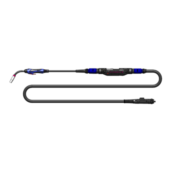
Summary of Contents for Abicor Binzel FreedomDrive Abimig AT355
- Page 1 T E C H N O L O G Y F O R T H E W E L D E R ’ S W O R L D . FreedomDrive FreedomDrive Push-Pull ™ MIG/MAG EN 60 974-7 Operating Instructions www.binzel-abicor.com...
-
Page 2: Table Of Contents
FreedomDrive Operating Instructions © The manufacturer reserves the right, at any time and without prior notice, to make such changes and amendments to these Operating Instructions which may become necessary due to misprints, inaccuracies or improvements to the product. Such changes will however be incorporated into subsequent editions of the Instructions. -
Page 3: Designated Use
FreedomDrive Designated Use The FreedomDrive hand-held welding MIG guns are used for welding of standard wire electrodes. They conform to EN 60 974-7 and are not considered devices having their own functions. Arc welding can only be carried out in connection with a welding power supply. These operating instructions only describe FreedomDrive welding MIG guns. -
Page 4: Abbreviations
Technical Data FreedomDrive 20 and 30 feet Standard length Cooling unit power min. 1200 W Multi-wire w/circular connector Control lead approx. 0.7 kg Weight/meter Machine-side connection Euro or Direct Tab. 4 Cable assembly Size Groove .030” / .035” (0.8 / 0.9 mm) 0.47”... -
Page 5: Safety Instructions
Safety Instructions FreedomDrive Safety Instruction Please observe the attached safety instructions. Classification The warning signs used in the operating instructions are divided into four different levels and are shown prior to specific work steps. Arranged in descending order of importance, they have the following meaning: DANGER Describes imminent threatening danger. -
Page 6: Putting Into Operation
Putting into operation FreedomDrive Putting into operation DANGER Risk of injury due to unexpected start-up. For the entire duration of maintenance, servicing, dismounting and repair work, the following instructions must be adhered to: • Switch off the power supply. • Close off the compressed gas supply. •... -
Page 7: Installing The Optional Neck
Putting into operation FreedomDrive Installing the optional neck liner in the air-cooled MIG gun neck The neck liners must be cut to length, according to the neck. Please be sure to order the correct neck liner in order to avoid feeding issues MIG gun Neck Neck Liner Fig. -
Page 8: Installing The Rear Cable Liner
FreedomDrive Installing the steel rear cable liner To be used for steel wires. Note • New unused liners have to be shortened to the actual length of the cable assembly. FreedomDrive cable assy Steel liner “Euro” Liner Collet Outlet viewing guide Steel liner pass-through Rear connector Liner retention nut... - Page 9 FreedomDrive Lincoln - Cut the steel liner flush with rear of liner retention nut ® Miller - Cut the steel liner such that the liner extends as close to the drive rolls as possible; ® typically 2 coils beyond the liner retention nut. Fig.
- Page 10 FreedomDrive Installing the plastic cable liner To be used for aluminum, copper, nickel, and stainless steel wires. Note • New unused liners have to be shortened to the actual length of the cable assembly. FreedomDrive cable assy Plastic liner Liner Collet Outlet viewing guide O-ring Rear connector...
-
Page 11: Installing The Front Cable Liner
FreedomDrive Installing the front cable liner Note • New unused liners have to be shortened to the actual length of the cable assembly. Front MIG gun Liner Steel Inlet guide Liner Marking Tool Liner Combi/PA Indication Groove Fig. 8 Front Cable Liner Installing Front Cable Liner: Note: New MIG guns are supplied with a pre-cut and bagged liner and do not need to be cut prior to install. -
Page 12: Connecting The Cable Assembly
FreedomDrive Connecting the cable assemblies FreedomDrive Rear Cable Back End Front Connector Fig. 9 FreedomDrive to Cable Connections The FreedomDrive unit is designed to pass through all operational functions; wire, gas, power, control, and water (water-cooled version only). The various pins and guides serve to align the mating surfaces during assembly. - Page 13 This may impair the service life of your welding MIG gun. • For liquid-cooled FreedomDrive welding MIG guns, we recommend using ABICOR BINZEL coolants. • Each time the device is commissioned or after each cable assembly change, the cooling system must be purged of any air: Disconnect the coolant return hose from the re-circulating cooling unit and hold it over a collecting device.
-
Page 14: Connecting The Freedomdrive Control Lead
FreedomDrive Connecting the FreedomDrive control lead Control Lead FreedomDrive Back End Fig. 10 Connecting the FreedomDrive Control Lead Note: Connection varies by machine. Connecting the FreedomDrive Control Lead: 1. Power source must be “off” and power cord disconnected from incoming power. -
Page 15: Feeding The Wire
FreedomDrive Feeding in the Wire Front Rear Fig. 11 Feeding in the Wire Feeding in the Wire: 1. Install the wire into the wire feeder as specified by the wire feeder manufac- turer. 2. Lay the MIG gun out as straight as possible. Open the access cover (2) on the FreedomDrive housing (1) by sliding it towards the rear of the housing. -
Page 16: Operating Elements
FreedomDrive Operating Control Elements Note • As the MIG/MAG welding MIG guns are integrated into a welding system, the operating instructions of the welding components, such as the welding power supply, must be observed during operation. 2-Cycle Trigger and Incher Function WARNING: The handle mounted trigger and FreedomDrive mounted wire inch buttons are connected. -
Page 17: Wire Feed Speed Knob In Mig
FreedomDrive Wire Feed Speed Knob in MIG gun Handle (option based on MIG gun selection - see ordering chart) Wire Feed Speed Knob Fig. 13 Wire Feed Speed Knob in MIG gun Handle 1. Rotate the wire feed speed knob in the direction of the ( - ) indicator (couter- clockwise) to reduce wire feed speed. -
Page 18: Putting Into Operation
FreedomDrive Putting into Operation 1. Open the shielding gas cylinder. 2. Switch on the power supply 3. Set the welding parameters. 4. Start welding. Note • Liquid-cooled hose assemblies will start leaking if the return coolant temperature is exceeded. Make sure not to exceed a return coolant temperature of 60˚... -
Page 19: Putting Out Of Operation
FreedomDrive Putting out operation Note • Liquid-cooled hose assemblies will start leaking if overheated. This is why the cooling unit should continue running for approx. 5 min. after welding. 1. Stop welding. 2. Wait until the shielding gas flow has subsided and then switch off the power supply. -
Page 20: Replacing The Drive Rolls
FreedomDrive Replacing the drive rolls a Fig. 11 Feeding in the wire on page 15. Note • Make sure that the drive rolls comply with the diameter of the inserted wire electrode. 1. Open the access cover (2) and unscrew the two slotted drive roll thumb screws. -
Page 21: Mig Gun Neck
FreedomDrive MIG gun neck 1. Remove gas nozzle. 2. Remove welding spatter and spray gas nozzle with ABICOR BINZEL anti- spatter agent or ceramic spray. 3. Check wear parts for visible damage and replace them, if required. 4. Replace the cable or neck liner (optional on air-cooled) when worn or soiled. -
Page 22: Troubleshooting
FreedomDrive Troubleshooting Note • If the measures described below are not successful, please consult your dealer or the manufacturer. • Please also consult the operating instructions for the welding components, such as power supply. Fault Cause Solution MIG gun neck or handle •... - Page 23 FreedomDrive Notes...
- Page 24 FreedomDrive ! Danger • Read and follow the manufacturer’s instructions, ELECTRIC SHOCK can kill. • Always wear dry insulating gloves. employer’s safety practices and Material Safety • Do not touch live electrical parts. Data Sheets (MSDSs). • Always disconnect power source before hooking up or changing elec- •...
Need help?
Do you have a question about the FreedomDrive Abimig AT355 and is the answer not in the manual?
Questions and answers