Advertisement
West Warwick, Rhode Island 02893
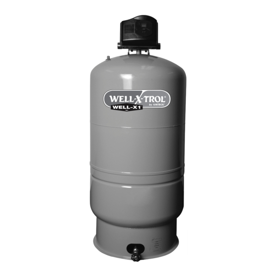
WELL-X-TROL
IMPORTANT GENERAL SAFETY INFORMATION - ADDITIONAL SPECIFIC SAFETY ALERTS APPEAR IN THE FOLLOWING INSTRUCTIONS.
READ CAREFULLY THE PRODUCT INSTALLATION, OPERATING AND MAINTENANCE MANUAL. FAILURE TO FOLLOW
THE INSTRUCTIONS AND WARNINGS IN THE MANUAL MAY RESULT IN SERIOUS OR FATAL INJURY AND/OR PROPERTY DAMAGE,
AND WILL VOID THE PRODUCT WARRANTY. THIS PRODUCT MUST BE INSTALLED BY A QUALIFIED PROFESSIONAL. FOLLOW ALL
APPLICABLE LOCAL AND STATE CODES AND REGULATIONS, IN THE ABSENCE OF SUCH CODES, FOLLOW THE CURRENT EDITIONS OF
THE NATIONAL PLUMBING CODE AND NATIONAL ELECTRIC CODE, AS APPLICABLE.
This is the safety alert symbol. It is used to alert you to personal injury hazards. Obey all safety instructions that follow this symbol to
reduce the risk of possible injury or death as well as property damage.
9013-0001 (3/08)
INSTALLATION, OPERATION
INSTALLER: LEAVE THIS MANUAL WITH THE OWNER
& MAINTENANCE
INSTRUCTIONS
WELL-X1
®
™
Advertisement
Table of Contents

Related Manuals for Amtrol WELL-X-TROL


Summary of Contents for Amtrol WELL-X-TROL
- Page 1 West Warwick, Rhode Island 02893 WELL-X-TROL INSTALLER: LEAVE THIS MANUAL WITH THE OWNER IMPORTANT GENERAL SAFETY INFORMATION - ADDITIONAL SPECIFIC SAFETY ALERTS APPEAR IN THE FOLLOWING INSTRUCTIONS. READ CAREFULLY THE PRODUCT INSTALLATION, OPERATING AND MAINTENANCE MANUAL. FAILURE TO FOLLOW THE INSTRUCTIONS AND WARNINGS IN THE MANUAL MAY RESULT IN SERIOUS OR FATAL INJURY AND/OR PROPERTY DAMAGE, AND WILL VOID THE PRODUCT WARRANTY.
-
Page 2: Table Of Contents
Current copies of the Product manual can be viewed at www.amtrol.com. Use proper safety equipment when installing. ELECTROCUTION AND EXPLOSION HAZARD! Before work is performed on the Product, turn off the power to the Product and release all pressure in the system. -
Page 3: Components
The Well-X1 combines all the standard well tank components in a single, easy to install package. The pressure tank, ™ control and tank fittings are factory-installed. After removing from the carton, inspect the Well-X1 ensure all components are present. CONDUIT HOLES AIR CHARGING VALVE PUMP &... -
Page 4: Installation And Sizing Considerations
4. INSTALLATION AND SIZING CONSIDERATIONS The Well-X1 functions like a traditional pressure switch by cycling the pump on and off. The factory pressure settings ™ are 40 psi cut-in and 60 psi cut-out. The controller allows these settings to be adjusted to best suit the application. The Well-X1 can operate in two primary modes: ™... -
Page 5: Installation Considerations
5. INSTALLATION CONSIDERATIONS LOCATION The Well-X1 is designed for indoor and outdoor installations. The NEMA 3R enclosure can be installed ™ in direct weather. If installed outdoors, be sure the following conditions are met: • Do not install where ambient temperatures can drop below freezing or exceed 120°... -
Page 6: Plumbing
1. Plumbing connections are similar to a traditional "tank cross" or "tank tee". Provisions are made for popular line sizes via a 1-1/4" NPT male outer thread and a 1" NPT female inner thread. The plumbing connections are not directional and allow flow from either side. When attaching valves or fittings, uses the wrench flats provided. - Page 7 4. Connect the water line from the well pump to the inlet of the Well-X1 ™ 5. Plumb the outgoing supply to the building's water supply system or into the water treatment equipment (if present). 6. Install a blow down tube from the relief valve to a drain or to within 6"...
-
Page 8: Wiring
1. Shut off the circuit breaker for the well system. Loosen the top screw housing cover. Flip the cover forward and remove to expose the control wires. Electrocution hazard. For your safety, the information in this manual must be followed to minimize the risk of electric shock, property damage or personal injury. -
Page 9: Startup & Adjustment
8. STARTUP & ADJUSTMENT 1. After plumbing and wiring are complete, close the service valve to allow startup without pressurizing the entire plumbing system. If a service valve was not installed, close all fixtures in the home. Ensure the bottom drain is closed. 2. - Page 10 8. STARTUP & ADJUSTMENT (con't) 5.The factory cut-out (pump off) setting is 60 psig. When the pump reaches 60 psig, the Well-X1 pump off. Check the plumbing for leaks and repair before continuing. If during startup the cut-out setting of 60 psig cannot be reached, read the adjustment instructions to lower the cut-out within the pump's capability.
- Page 11 PRESSURE ADJUSTMENT The Well-X1 ™ utilizes a simple cut-in/cut-out adjustment. Before setting the desired operating range, refer to the chart below to ensure the Well-X1's Maximum Acceptance is not exceeded. Adjust the precharge as shown on page 12. CAUTION! Exceeding Maximum Acceptance will reduce tank life and cause irreparable damage. Step 1: Find the Maximum Acceptance for the installed Well-X1 model.
- Page 12 3. To adjust the cut-out, depress MODE once and the display will read HI. Again, press the to raise or lower the setting. The same 10-55 psig differential range applies. Maximum setting is 80 psig. 4. After adjusting the cut-in and cut-out, release the buttons.
-
Page 13: Pump Protection & Diagnostics
9. PUMP PROTECTION AND DIAGNOSTICS The Well-X1 continually monitors pressure, cycle time and voltage to protect the well pump. The following error codes ™ alert the user to a potential problem, prompting service. E1: Rapid Cycle E2: Low Suction (low water cut-off) E3: Voltage Protection E5: Improper Wiring WELL-X1... -
Page 14: Troubleshooting
10. TROUBLESHOOTING PROBLEM POSSIBLE CAUSE Alarm sounds 1. Error encountered No water at fixtures 1. Error encountered 2. No power 3. Water line obstructed 4. Faulty pump 5. Drain or relief valve open 6. Leak in plumbing Low water pressure 1. -
Page 15: Replacement Parts
11. REPLACEMENT PARTS DESCRIPTION POSITION Replacement tank: Blue Replacement tank: Tuf Kote™ Electronic control (no cover) Control cover Mounting bracket Brass tee only (no accessories) Pressure sensor tubing Pressure sensor fitting (elbow) Pressure sensor fitting (straight) Tank tubing replacement kit w/fitting Relief valve, 100 psig Drain assembly Mounting knob... - Page 16 What is covered by this Warranty AMTROL warrants to the purchaser or first user of the new Product that at the time of manufacture, the Product is free from defects in material and workmanship. Any warranty claim must be made within one (1) year unless another time period is set forth in the Manual, measured from the time the Product was purchased.
Need help?
Do you have a question about the WELL-X-TROL and is the answer not in the manual?
Questions and answers