Table of Contents
Advertisement
West Warwick, Rhode Island 02893
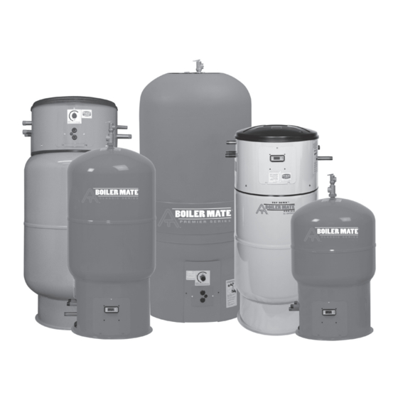
INDIRECT-FIRED WATER HEATERS
MODELS COVERED:
• WH-7 & 9 Classic Series
• Top Down
• RTR models
• WHS Premier Series
INSTALLER: LEAVE THIS MANUAL WITH THE OWNER
IMPORTANT GENERAL SAFETY INFORMATION - ADDITIONAL SPECIFIC SAFETY ALERTS APPEAR IN THE FOLLOWING
INSTRUCTIONS.
READ CAREFULLY THE PRODUCT INSTALLATION, OPERATING AND MAINTENANCE MANUAL. FAILURE
TO FOLLOW THE INSTRUCTIONS AND WARNINGS IN THE MANUAL MAY RESULT IN SERIOUS OR
FATAL INJURY AND/OR PROPERTY DAMAGE, AND WILL VOID THE PRODUCT WARRANTY. THIS PRODUCT MUST BE
INSTALLED BY A QUALIFIED PROFESSIONAL. FOLLOW ALL APPLICABLE LOCAL AND STATE CODES AND REGULATIONS,
IN THE ABSENCE OF SUCH CODES, FOLLOW THE CURRENT EDITIONS OF THE NATIONAL PLUMBING CODE AND NATIONAL
ELECTRIC CODE, AS APPLICABLE.
THIS IS THE SAFETY ALERT SYMBOL. IT IS USED TO ALERT YOU TO POTENTIAL PERSONAL INJURY AND OTHER
HAZARDS. OBEY ALL SAFETY MESSAGES THAT FOLLOW THIS SYMBOL TO REDUCE THE RISK OF PERSONAL
INJURY AS WELL AS PROPERTY DAMAGE.
The heat transfer medium must be water or other nontoxic fluid having a toxicity rating or class of 1, as
listed in Clinical Toxicology of Commercial Products, 5th edition. The pressure of the heat transfer
medium must be limited to 30 PSIG by an approved safety or relief valve.
Part #: 9040-586 (07/08)
INSTALLATION, OPERATION
BOILERMATE
TD Series
™
& MAINTENANCE
INSTRUCTIONS
®
MODELS CODES:
P:
Packaged with circulator & Smart Control
L:
Less Circulator, with Smart Control
Z:
Dial Aquastat
C:
High-output commercial exchanger
DW: Double-wall heat exchanger
RTR: Pre-piped and wired
™
™
Advertisement
Table of Contents

Related Manuals for Amtrol BoilerMate RTR


Summary of Contents for Amtrol BoilerMate RTR
- Page 1 West Warwick, Rhode Island 02893 INDIRECT-FIRED WATER HEATERS MODELS COVERED: • WH-7 & 9 Classic Series • Top Down • RTR models • WHS Premier Series INSTALLER: LEAVE THIS MANUAL WITH THE OWNER IMPORTANT GENERAL SAFETY INFORMATION - ADDITIONAL SPECIFIC SAFETY ALERTS APPEAR IN THE FOLLOWING INSTRUCTIONS.
-
Page 2: Table Of Contents
2. Pre-Installation Checklist ... 3. Required Components and Accessories Checklist ... 4. WH-7 & 9 Classic Series Piping Installation ... 5. Top Down™ TD-Series Piping Installation ... 6. Ready-To-Run RTR-Series Piping Installation ... 7. WHS Premier Series Piping Installation ... 8. -
Page 3: Required Components And Accessories Checklist
SEE HEAT EXCHANGER PRESSURE DROP CHART TO DETERMINE PUMP HEAD REQUIREMENTS. Use this chart to select the proper circulator for your BOILERMATE If a steel hydropneumatic tank is in place, AMTROL properly sized EXTROL heat transfer problems can occur by causing air to be trapped in the heat exchanger. If the boiler system has... -
Page 4: Classic Series Piping Installation
PIPING INSTALLATION DOMESTIC WATER PIPING 1. Thread the included ” brass tee onto the pipe marked COLD WATER. 2. Screw the ” drain valve into the opposite end of the brass tee. 3. Connect the cold water supply to the remaining port on the brass tee. - Page 5 PIPING USING SEPARATE CIRCULATOR PUMP (RECOMMENDED) PIPING USING ZONE VALVE WITH EXISTING HEATING SYSTEM CIRCULATOR...
-
Page 6: Top Down™ Td-Series Piping Installation
5. TOP DOWN™ TD-SERIES PIPING INSTALLATION DOMESTIC WATER PIPING 1. Connect the cold water supply to the pipe labeled COLD WATER 2. Connect the HOT WATER piping to the domestic hot water system. 3. Make an 8-inch “heat trap” on the HOT WATER outlet as shown in the diagram. - Page 7 PIPING USING SEPARATE CIRCULATOR PUMP (RECOMMENDED) PIPING USING ZONE VALVE WITH EXISTING HEATING SYSTEM CIRCULATOR...
-
Page 8: Ready-To-Run Rtr-Series Piping Installation
6. READY-TO-RUN RTR-SERIES PIPING INSTALLATION DOMESTIC WATER PIPING 1. Connect the cold water supply to the pipe labeled COLD WATER. 2. Connect the HOT WATER piping to the domestic hot water system. 3. Make an 8-inch “heat trap” on the HOT WATER outlet as shown in the diagram. - Page 9 PIPING MODELS WITH PRE-INSTALLED CIRCULATOR W/INTEGRAL FLOW CHECK...
-
Page 10: Whs Premier Series Piping Installation
7. WHS PREMIER SERIES PIPING INSTALLATION DOMESTIC WATER PIPING 1. Thread the included brass tee onto the pipe marked COLD WATER. 2. Screw the drain valve into the opposite end of the brass 3. Connect the cold water supply to the remaining port on the brass tee 4. - Page 11 PIPING USING SEPARATE CIRCULATOR PUMP (RECOMMENDED) PIPING USING ZONE VALVE WITH EXISTING HEATING SYSTEM CIRCULATOR -11-...
-
Page 12: Wiring All Smart Control™ Models
The Smart Control™ incorporates all the switching and temperature control functions necessary to control the BoilerMate™. The diagram below shows internal wiring and the associated functions. After wiring is complete, insert the white thermistor (sensor) plug into the receptacle at the base of the Smart Control™. Select the plug marked CIRCULATOR or ZONE VALVE based on the application. - Page 13 L8124 A & C L8124 B & D LOW LIMIT/ HIGH CIRCULATOR LIMIT L1 L2 L8148A HIGH LIMIT HONEYWELL L8148A BOILERMATE ® CIRCULATOR HONEYWELL L8124 A & C BOILERMATE ® CIRCULATOR HONEYWELL L8124 B & D L1 L2 BOILERMATE CIRCULATOR -13- BOILERMATE ®...
- Page 14 L8148J W TV LIMIT C1 C2 B1 B2 B3 L1 L2 L1 L2 L8148J W TV LIMIT C1 C2 B1 B2 B3 L1 L2 L1 L2 8J48A WHITE - RODGERS 8J48A WITH 24 VOLT GAS VALVE BOILERMATE JUNCTION BOX (PLACE A WIRE NUT OVER EACH WIRE NOT USED) BOILERMATE ®...
- Page 15 8J48A WHITE - RODGERS 8J48A WITH SELF-GENERATING GAS VALVE L8124 A & C HEATING CIRCULATOR L8124 B & D HIGH LOW LIMIT/ LIMIT CIRCULATOR HEATING CIRCULATOR BOILERMATE ® CIRCULATOR PRIORITY WIRING HONEYWELL L8124 A & C BOILERMATE ® HONEYWELL L8124 B & D CIRCULATOR -15- BOILERMATE...
- Page 16 L8148A HIGH LIMIT L8148B HIGH LIMIT L8148J TP Z LIMIT C1 C2 B1 B2 BOILERMATE JUNCTION BOX PRIORITY WIRING BOILERMATE ® HONEYWELL L8148A CIRCULATOR L1 L2 BOILERMATE ® CIRCULATOR PRIORITY WIRING HONEYWELL L8148B BOILERMATE ® HONEYWELL L8148 J CIRCULATOR -16- ®...
- Page 17 L8148J TP Z LIMIT C1 C2 B1 B2 8J48A PRIORITY WIRING WHITE-RODGERS 8J48A WITH 24VOLT GAS VALVE 8J48A PRIORITY WIRING WHITE-RODGERS 8J48A WITH SELF-GENERATING GAS VALVE BOILERMATE JUNCTION BOX ORANGE ORANGE BLUE BLUE VIOLET VIOLET WHITE BLACK PRIORITY WIRING BOILERMATE ®...
- Page 18 Typical Multi-Zone Relay Utilizing Post-Purge Feature Thermostat Inputs Priority or DHW Zone Zone Outputs BoilerMate Boiler Aquastat Circulator Typical Multi-Zone Relay 24V without Post-Purge Feature Thermostat Inputs Priority or DHW Zone Supply Zone Outputs BoilerMate Boiler Aquastat Circulator ORANGE ORANGE BLUE BLUE VIOLET...
- Page 19 The Smart Control™ features an error code designed to alert the user to the presence of water on the floor. This is useful to warn of a leaking boiler, water heater, etc., or to alert the owner to a leak in the basement. If equipped with the optional water...
-
Page 20: Wiring All Dial Control Models
To wire Dial Control models, select the appropriate diagram from the following pages. If a suitable diagram is not available for your application, please contact AMTROL Tech Support at (401)535-1216. Always disconnect power before wiring the control. Ensure that the proper conduit and connectors are used per your local code. In lieu of local code, the National Electric Code should be followed. - Page 21 ZONE VALVES - SCHEMATIC 3 3-WIRE ZONE VALVES PRIORITY W/CIRCULATORS - SCHEMATIC 4 Typical Multi-Zone Relay Thermostat Inputs BoilerMate Thermostat ® Priority or DHW Zone Zone Outputs Boiler Aquastat BoilerMate ® Circulator -21-...
- Page 22 SMART CONTROL™ JUNCTION BOX ORANGE ORANGE BLUE BLUE VIOLET VIOLET BLACK WHITE (PLACE A WIRE NUT OVER EACH WIRE NOT USED IN THE AMTROL BOILER MATE ® JUNCTION BOX.) SMART CONTROL™ JUNCTION BOX ORANGE ORANGE BLUE BLUE VIOLET VIOLET BLACK...
-
Page 23: Wiring All Ready-To-Run (Rtr) Models
To wire RTR models, select the appropriate diagram from the following pages. If a suitable diagram is not available for your application, please contact AMTROL Tech Support at (401)535-1216. Always disconnect power before wiring the unit. Ensure that the proper conduit and connections are used per your local code. In lieu of local code, the National Electric Code should be followed. - Page 24 CIRCULATOR RELAY BOX Indirect Aquastat HEATING CIRCULATOR HONEYWELL L8148A OR SIMILAR W/PRIORITY CIRCULATOR RELAY BOX Indirect Aquastat WHITE RODGERS 8J48A W/24V GAS VALVE LIVE NEUT Indirect Aquastat REMOVE JUMPER BETWEEN 1 & 3 HONEYWELL L8148J W/MILLIVOLT GAS VALVE LIVE NEUT Indirect Aquastat THERMOSTATS...
-
Page 25: Startup Procedure For All Models
11. STARTUP PROCEDURE FOR ALL MODELS 1. PURGE HEAT EXCHANGER: The heat exchanger should be free of large air pockets to allow the circulator to operate properly. Using the diagram below as a guide, isolate the boiler return line and flush the loop until large air pockets are purged. -
Page 26: Setting The Smart Control
To raise or lower this temperature setpoint, press the s or t pushbutton. The temperature can be set between 90°F and 150°F. To shut the unit down, scroll below 90°F until 0°F is displayed. Shutting the unit down is beneficial if the water heater will not be used for an extended period of time. -
Page 27: Troubleshooting
PROBLEM 1. No power to unit 2. Air in heat exchanger loop 3. Faulty circulator or zone valve 4. Faulty BoilerMate™ thermostat No hot water 5. Faulty Smart Control™ 6. Boiler inoperable 1. Demand exceeds capacity 2. Temperature too low 3. -
Page 28: Replacement Parts
Dial Aquastat Circulator Pump 245-58 Water Sensor 2704-495 To obtain replacement parts, contact the installer or place of purchase. Technical support is available by calling AMTROL at (401) 535-1216. WHS 60 & 80 TD-7 Series TD-7 RTR TD-80 Series Residential... -
Page 29: Cleaning The Boilermate
15. CLEANING THE BOILERMATE HEAT EXCHANGER COIL A diminished temperature difference between the boiler water entering and leaving the heat exchanger coil may indicate heat exchanger scale buildup. Water treatment equipment and proper maintenance will help to avoid this problem. To clean a scaled heat exchanger coil proceed as follows: Shut off the cold water supply to the... -
Page 30: General Safety Information
Current copies of the Product manual can be viewed at www.amtrol. com. Use proper safety equipment when installing. to a maximum of 30 psig by an approved safety or relief valve on your boiler. - Page 31 -31-...
- Page 32 West Warwick, Rhode Island 02893 Boiler Mate, AMTROL, AMTROL logo, Therm-X-Trol, Radiant EXTROL and EXTROL are registered trademarks of AMTROL Inc. and affiliates. All rights reserved. Part #: 9040-586 (07/08)
Need help?
Do you have a question about the BoilerMate RTR and is the answer not in the manual?
Questions and answers