Advertisement
PLEASE READ THE FOLLOWING INSTRUCTIONS CAREFULLY
IMPORTANT GENERAL SAFETY INFORMATION - ADDITIONAL SPECIFIC SAFETY ALERTS APPEAR IN THE
FOLLOWING INSTRUCTIONS.
DO NOT LIFT OR CARRY WATER HEATER BY THE TOP COVER. WATER HEATER DAMAGE OR PERSONAL
INJURY MAY OCCUR IF THE COVER BECOMES DETACHED.
READ CAREFULLY THE PRODUCT INSTALLATION, OPERATING AND MAINTENANCE MANUAL. FAILURE
TO FOLLOW THE INSTRUCTIONS AND WARNINGS IN THE MANUAL MAY RESULT IN SERIOUS OR FATAL
INJURY AND/OR PROPERTY DAMAGE, AND WILL VOID THE PRODUCT WARRANTY. THIS PRODUCT MUST BE INSTALLED
BY A QUALIFIED PROFESSIONAL. FOLLOW ALL APPLICABLE LOCAL AND STATE CODES AND REGULATIONS. IN THE
ABSENCE OF SUCH CODES, FOLLOW THE CURRENT EDITIONS OF THE NATIONAL PLUMBING CODE AND NATIONAL
ELECTRIC CODE, AS APPLICABLE.
THIS IS THE SAFETY ALERT SYMBOL. IT IS USED TO ALERT YOU TO POTENTIAL PERSONAL INJURY AND OTHER
HAZARDS. OBEY ALL SAFETY MESSAGES THAT FOLLOW THIS SYMBOL TO REDUCE THE RISK OF PERSONAL
INJURY AS WELL AS PROPERTY DAMAGE.
The heat transfer medium must be water or other nontoxic fluid having a toxicity rating or class of 1, as
listed in Clinical Toxicology of Commercial Products, 5th edition. The pressure of the heat transfer
medium must be limited to 30 PSIG by an approved safety or relief valve.
9040-694 (10/11)
INSTALLATION & OPERATION INSTRUCTIONS
1400 Division Road, West Warwick, RI 02893
INSTALLER: LEAVE THIS MANUAL WITH THE OWNER
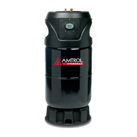
HM-41Z & HM-80Z (Mechanical Control)
HM-41L & HM-80L (Ener-G-NET™ Digital Control)
INDIRECT-FIRED WATER HEATERS
T: 401.884.6300
Models Covered:
HYDROMAX
F: 401.885.2567
www.amtrol.com
™
Advertisement
Table of Contents

Subscribe to Our Youtube Channel
Related Manuals for Amtrol HYDROMAX HM-41L


Summary of Contents for Amtrol HYDROMAX HM-41L
- Page 1 ™ INDIRECT-FIRED WATER HEATERS 1400 Division Road, West Warwick, RI 02893 T: 401.884.6300 F: 401.885.2567 www.amtrol.com PLEASE READ THE FOLLOWING INSTRUCTIONS CAREFULLY INSTALLER: LEAVE THIS MANUAL WITH THE OWNER Models Covered: HM-41Z & HM-80Z (Mechanical Control) HM-41L & HM-80L (Ener-G-NET™ Digital Control) IMPORTANT GENERAL SAFETY INFORMATION - ADDITIONAL SPECIFIC SAFETY ALERTS APPEAR IN THE FOLLOWING INSTRUCTIONS.
-
Page 2: Table Of Contents
1. Table Of Contents 2. Pre-Installation Checklist ..........7. Mechanical Aquastat Wiring .......... 3. Required Components and Accessories Checklist ..8. Startup Procedure ............4. HYDROMAX Plumbing ..........9. Troubleshooting ............. ™ 5. Ener-G-NET Wiring ..........10. General Safety Information ......... ™... -
Page 3: Required Components And Accessories Checklist
3. Required Components And Accessories Checklist THERMAL CIRCULATOR SHUTOFF MODEL ZONE VALVE RELIEF VALVE EXPANSION PERFORMANCE VALVES TANK HM-41 5 GPM @ 7 FT 3/4” Full Port Included 2.0 Gallon HM-80 5 GPM @ 7 FT 3/4” Full Port Included 4.4 Gallon If a steel hydropneumatic tank is in place, replace it with a properly sized diaphragm expansion tank. -
Page 4: Hydromax ™ Plumbing
4. HYDROMAX Plumbing ™ DOMESTIC WATER PIPING Do not drill, puncture or otherwise penetrate the steel outer tank shell. 1. Connect the cold water supply to the pipe labeled Do not screw pipe hangers or other hardware into the COLD WATER. exterior of the tank. - Page 5 5. Ener-G-NET Wiring ™ Ener-G-NET incorporates all of the temperature sensing and control necessary for HYDROMAX™ operation. Built-in switching relays may be wired to operate the boiler control and circulator pump or zone valve. The diagram below illustrates these internal switching functions.
-
Page 6: Ener-G-Net ™ Wiring
Common wiring diagrams are shown below. Select the appropriate diagram for the application. Diagrams are popular examples only. If your application is not shown, contact Amtrol Technical Support at 401.535.1216. NOTE: Ensure the Ener-G-NET installation is within the following application and operating parameters: • Ambient temperature from 38° to 125°F... -
Page 7: Ener-G-Net ™ Setup & Adjustment
6. Ener-G-NET Control Setup & Adjustment ™ Mode Indicators Ener-G-NET features two distinct programming areas: User Modes and Installer Settings. User Modes consist of three end-user functional User modes, while Installer Settings are primarily accessed upon initial setup Modes to specify critical operating parameters. Ener-G-NET factory defaults Display allow traditional operation suitable for most homes. -
Page 8: Mechanical Aquastat Wiring
7. Mechanical Aquastat Wiring Diagrams Common wiring diagrams are shown below. Select the appropriate diagram for the application. Diagrams are popular examples only. If your application is not shown, contact Amtrol Technical Support at 401.535.1216. Boiler Controls Typical Gas Valves (Non-Priority) -
Page 9: Startup Procedure
8. Startup Procedure 1. PURGE HEAT EXCHANGER: The heat exchanger should be free of large air pockets to allow the circulator to operate properly. Using the diagram below as a guide, isolate the boiler return line and flush the loop until large air pockets are purged. After this, the air elimination equipment will collect smaller air bubbles. -
Page 10: General Safety Information
For more information: manual. Contact your water supplier or local plumbing inspector for www.amtrol.com/prop65.htm additional information. As in all plumbing products and water storage... -
Page 11: Replacement Parts
11. REPLACEMENT PARTS Description HM-41 Models HM-80 Models Heat Exchanger Replacement Kit 2713R002 2712R002 Top Cover Half (2 Required) 2704R512 2704R512 Mounting Panel, Digital Control 2704R525 2704R525 Mounting Panel, Mechanical Control 2704R498 2704R498 Ener-G-NET™ Digital Temperature Control 940R2 940R2 Temperature Sensor (Thermistor) 2704-259 2704-259 Water Sensor... - Page 12 1400 Division Road, West Warwick, RI 02893 T: 401.884.6300 F: 401.885.2567 www.amtrol.com HYDROMAX, Ener-G-NET, AMTROL, AMTROL logo, Therm-X-Trol, and EXTROL are registered trademarks of AMTROL Inc. and affiliates in the U.S. and elsewhere. All rights reserved. 9040-694 (10/11)
Need help?
Do you have a question about the HYDROMAX HM-41L and is the answer not in the manual?
Questions and answers