Advertisement
12-24V
3G/LTE ANTENNA
AUDIO MICROPHONE
PACKAGE CONTENTS
Power Specifications | Input: DC 10~32V, 2000mA Output: DC5V, 2500mA
Getting Started
Park the vehicle on a flat surface and ensure the engine is off.
STEP 1
MOUNT CP4 LOCKING ENCLOSURE
Find a location for the CP4 recorder Box and Locking enclosure. Example: Under Drivers Seat.
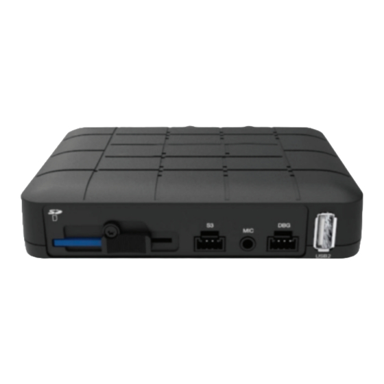
Ensure locking enclosure is securely affixed to the vehicle in a level horizontal position with SD
card facing the REAR of the vehicle.
Ensure client will have access to unlock enclosure to access the SD card.
CP4 RECORDER
CAMERA INPUT CABLE
POWER CABLE
REMOTE CONTROL
GPS ANTENNA
WIRE CLIPS + VELCRO
QUICK INSTALL
CP4
GUIDE
CERTIFIED
TRACKING
SOLUTIONS
CALL TO TEST THE DEVICE BEFORE CLOSING UP
DASH. FAILURE TO FOLLOW INSTRUCTIONS MAY
DAMAGE EQUIPMENT AND VOID WARRANTY
1.780.391.3800
TOLL FREE 1.855.287.4477 (CTS4GPS)
A/V OUTPUT CABLE
LOCKING ENCLOSURE
CAMERA EXTENSION CABLE(S)
Advertisement
Table of Contents

Related Manuals for TitanGPS CP4


Summary of Contents for TitanGPS CP4
- Page 1 STEP 1 MOUNT CP4 LOCKING ENCLOSURE Find a location for the CP4 recorder Box and Locking enclosure. Example: Under Drivers Seat. Ensure locking enclosure is securely affixed to the vehicle in a level horizontal position with SD card facing the REAR of the vehicle.
-
Page 2: Windshield Mounting
STEP 4 MOUNT CAMERA(S) The CP4 can accommodate up to four cameras. These can be a combination of indoor and/or outdoor cameras. We recommend consulting with the client as to their preferred mounting location(s) and camera angle(s). Please see below for some mounting suggestions;... -
Page 3: Wiring Connections
QUICK INSTALL GUIDE Wiring Connections Confirm with the client as to which optional connections are required. Required connections include Power, Ground and Ignition. Optional connections are listed below. IMPORTANT: Ensure that any mounting location does not interfere with any vehicle operations including airbags or driver line of sight. - Page 4 STEP 5 CONNECT IGNITION In order to function properly the device needs to be connected to a suitable “True” Ignition source This source has battery voltage whenever the vehicle is turned on and zero volts whenever the vehicle is turned off. This source does NOT drop in voltage during crank.
- Page 5 STEP 10 ROUTE AND CONNECT HARNESSES a) Route and connect Camera Input Harness (4ch) to "Video In" input on CP4 Recorder Box. b) Route and connect Remote Control to "Remote" input on CP4 Recorder Box. c) Route and connect GPS Antenna to "GPS Input" on CP4 Recorder Box.
-
Page 6: Step 11 G-Sensor Calibration
COMPLETE FINAL CABLE ROUTING AND CLOSE LOCKING ENCLOSURE a) Insert CP4 into Locking Enclosure CP4 must be level AND horizontal with correct side skyward AND SD Card slot facing the REAR of the vehicle. CP4 must be accessible so the client can unlock and access the SD Card. -
Page 7: Administrative Details
QUICK INSTALL GUIDE STEP 14 ADMINISTRATIVE DETAILS Give provided locking keys and any extra parts/accessories to the fleet owner/administrator. - Page 8 powered by: Certified Tracking Solutions 1.780.391.3800 TOLL FREE 1.855.287.4477 (CTS4GPS)
Need help?
Do you have a question about the CP4 and is the answer not in the manual?
Questions and answers