Table of Contents
Advertisement
Quick Links
Advertisement
Table of Contents

Related Manuals for OBSIDIAN CONTROL SYSTEMS NETRON EP2


Summary of Contents for OBSIDIAN CONTROL SYSTEMS NETRON EP2
- Page 2 ©2021 OBSIDIAN CONTROL SYSTEMS all rights reserved. Information, specifications, diagrams, images, and instructions herein are subject to change without notice. Obsidian Control Systems logo and identifying product names and numbers herein are trademarks of ADJ PRODUCTS LLC. Copyright protection claimed includes all forms and matters of copyrightable materials and information now allowed by statutory or judicial law or hereinafter granted.
-
Page 3: Table Of Contents
C O N T E N T S GENERAL INFORMATION LIMITED WARRANTY SAFETY GUIDELINES OVERVIEW INSTALLATION CONNECTIONS MAINTENANCE SPECIFICATIONS DIMENSIONS... -
Page 4: General Information
G E N E R A L I N F O R M AT I O N INTRODUCTION Please read and understand the instructions in this manual carefully and thoroughly before attempting to operate this device. These instructions contain important safety and use information. UNPACKING Every device has been thoroughly tested and has been shipped in perfect operating condition. -
Page 5: Limited Warranty
(including negligence), misrepresentation, strict liability, breach of warranty of Elation or Obsidian Control Systems or any supplier, and even if Elation or Obsidian Control Systems or any supplier has been advised of the possibility of such damages. -
Page 6: Safety Guidelines
This device is a sophisticated piece of electronic equipment. To guarantee a smooth operation, it is important to follow all instructions and guidelines in this manual. OBSIDIAN CONTROL SYSTEMS is not responsible for injury and/or damages resulting from the misuse of this device due to the disregard of the information printed in this manual. -
Page 7: Overview
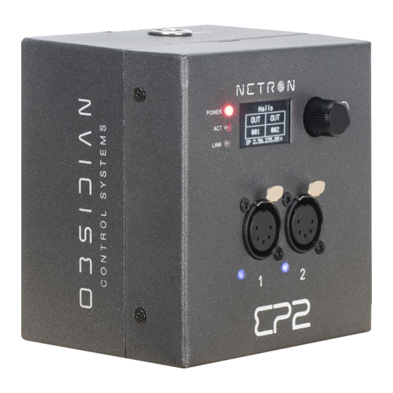
O V E R V I E W The NETRON EP2 is The Netron EP2 is a compact Ethernet to DMX gateway with two RDM compatible ports designed for wall mount, truss mount and standalone installations. It is configurable via its internal web remote and powered over Ethernet or via the convenient USB-C connection. -
Page 8: Installation
I N S TA L L AT I O N I N S T R U C T I O N S DISCONNECT POWER BEFORE PERFORMING ANY MAINTENANCE! ELECTRICAL CONNECTIONS A qualified electrician should be used for all electrical connections and/or installations. USE CAUTION WHEN POWER LINKING OTHER MODEL DEVICES AS THE POWER CONSUMPTION OF OTHER MODEL DEVICES MAY EXCEED THE MAXIMUM POWER OUTPUT OF THIS DEVICE. - Page 9 I N S TA L L AT I O N I N S T R U C T I O N S CLAMP INSTALLATION Insert 18.8 steel M10x25mm or M12x25mm bolt (not included) through the respective mounting hole of the clamp (not included), and then thread it into the matching 10M hole on top, or 12M hole on bottom.
- Page 10 I N S TA L L AT I O N I N S T R U C T I O N S Wall-Mount/Panel Installation: Chassis Disassembly The wall-mount/panel installation option requires the control panel to be removed from the mounting case, the internal multi-use mounting-bracket removed, and then remounted to the junction box.
- Page 11 I N S TA L L AT I O N I N S T R U C T I O N S Wall-Mount/Panel Installation: Junction Box 1. Mount and secure the internal multi-use mounting- bracket to the junction-box. All wiring and connections must be performed by a qualified electrician.
- Page 12 I N S TA L L AT I O N I N S T R U C T I O N S Wall-Mount/Panel Installation: American Standard Socket Junction Box 1. Mount and secure the internal multi-use mounting- bracket to the junction-box. All wiring and connections must be performed by a qualified electrician.
- Page 13 I N S TA L L AT I O N I N S T R U C T I O N S Wall-Mount/Panel Installation: Chassis Reassembly To reconfigure the EP2 to its original form, remount the internal multi-use mounting-bracket to the case and secure it with (4) hex-screws.
-
Page 14: Connections
C O N N E C T I O N S POWER CONNECTIONS The Obsidian Control Systems Netron EP2 is powered through USB-C or POE. DMX CONNECTIONS: All DMX Output connections are 5pin female XLR; the pin-out on all sockets is pin 1 to shield, pin 2 to cold (-), and pin 3 to hot (+). - Page 15 C O N N E C T I O N S : F R O N T & S I D E PA N E L S F R O N T C O N N E C T I O N S Turn to scroll, push-to-select Status Indicators...
-
Page 16: Maintenance
M A I N T E N A N C E The Obsidian Control Systems Netron EP2 is designed as rugged, roadworthy device. The only required service is occasional cleaning. For other service-related concerns, please contact your Obsidian Control Systems dealer, or visit www.obsidiancontrol.com. -
Page 17: Specifications
S P E C I F I C AT I O N S Connections Front (2) 5pin DMX/RDM optically isolated ports. Ports are bidirectional for DMX In and Output Side (1) Locking RJ45 Ethernet network connections (POE), USB-C power option (5V, 2A) Physical Length: 4.6 in. -
Page 18: Dimensions
D I M E N S I O N S...
Need help?
Do you have a question about the NETRON EP2 and is the answer not in the manual?
Questions and answers