
Related Manuals for Nortel BCM50 3.0


Summary of Contents for Nortel BCM50 3.0
- Page 1 Installation Checklist and Quick Start Guide BCM50 3.0 Business Communications Manager Document Status: Standard Document Number: NN40020-308 Document Version: 02.01 Part Code: N0107120 Date: August 2007...
- Page 2 Nortel Networks. Trademarks Nortel, the Nortel logo, and the Globemark are trademarks of Nortel Networks. Microsoft, MS, MS-DOS, Windows, and Windows NT are trademarks of Microsoft Corporation. All other trademarks and registered trademarks are the property of their respective owners.
- Page 3 THE TERMS OF THIS LICENSE. IF YOU DO NOT AGREE TO THE TERMS OF THIS LICENSE, RETURN THE UNUSED SOFTWARE AND THE ASSOCIATED DOCUMENTATION TO NORTEL NETWORKS THROUGH A NORTEL NETWORKS AUTHORIZED DISTRIBUTOR WITHIN FIVE (5) DAYS OF YOUR ACQUISITION OF THE SOFTWARE FOR A REFUND.
- Page 4 License. NORTEL NETWORKS. If NORTEL NETWORKS (i) claims a material breach of this License, and (ii) provides written notice of such claimed material breach to CUSTOMER and (iii) observes that such claimed material breach remains uncorrected and/or unmitigated more than thirty (30) days following CUSTOMER’s receipt of written notice specifying in reasonable detail...
-
Page 5: Table Of Contents
Nortel Business Element Manager ........ - Page 6 Contents BCM50 main unit LAN connection ........33 DHCP server configuration and IP address .
-
Page 7: Getting Started
For more information about installing and configuring a BCM50 system, see the Installation and Maintenance Guide. Precautions Nortel recommends that you read this entire document before starting the described procedures. Observe the general safety precautions against personal injury and equipment damage outlined in the Regional Installation Safety Manual (ISM) at all times. -
Page 8: Installation And Configuration Summary
Chapter 1 Getting started Installation and configuration summary The table Installation and configuration checklist on page 8 provides the tasks to install and configure a BCM50 system. Table 1 Installation and configuration checklist (Sheet 1 of 2) Task Reference Comments 5 min Review the BCM50 system hardware System overview on page 13... -
Page 9: Default Values
Chapter 1 Getting started Table 1 Installation and configuration checklist (Sheet 2 of 2) Task Reference Comments Apply the keycode. Software keycode on page 39 Configure the required BCM50 System parameters on page system parameters (Element Manager or Startup Profile). 1 min Configure the MBMs with Element MBM configuration on page... -
Page 10: Tools And System Information
Chapter 1 Getting started Tools and system information Use the table Tools on page 10 and the table System information on page 10 to record values and comments about tools and system information. Table 4 Tools Description Value Comments Laptop (or PC) with: •... -
Page 11: Checklists
Chapter 1 Getting started Table 5 System information (Sheet 2 of 2) Description Value Comments Fractional T1 channel numbers Frame relay DLCI/CIR (if applicable) V.90 modem settings (North America only) SNMP agent (security, version) SNMP manager IP address SNMP community string Checklists Before installing the BCM50 hardware, complete the following checklists. -
Page 12: Expansion Unit And Media Bay Modules Components Checklist (Optional)
Chapter 1 Getting started Expansion unit and media bay modules components checklist (optional) 5 minutes Check that you have the following components, and inspect the components for any damage: one expansion unit one expansion unit power supply one power-supply cable one expansion cable (shielded Ethernet cable) one power-supply retention clip four rubber feet... -
Page 13: System Overview
Expansion units and media bay modules on page 15 • Additional hardware on page 15 • Nortel Business Element Manager on page 16 • Startup Profile on page 16 For more information, see the chapter “Introducing the BCM50 hardware” in the Installation and Maintenance Guide. -
Page 14: Bri Main Units
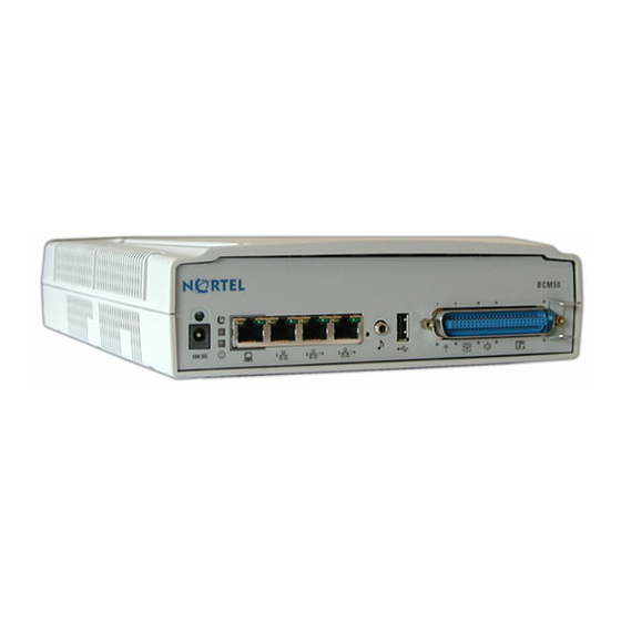
Chapter 2 System overview Figure 1 Standard main unit (BCM50e shown) ports and connectors Additional LAN Retention-clip mounting hole Power RJ-21 telephony Music Reset Expansion/LAN connector source (port 0) (port 1) switch (port 2, port 3) BRI main units The table BRI main units descriptions on page 14 describes the standard main units, and the figure BRI main unit (BCM50be shown) ports and connectors... -
Page 15: Expansion Units And Media Bay Modules
Chapter 2 System overview Expansion units and media bay modules The BCM50 system includes up to two expansion units. The expansion unit is designed to accommodate one media bay module (MBM) to connect additional telephony equipment to the system. The MBMs connect with external devices to implement various trunks and stations. The table Trunk, station, and combination MBMs on page 15 lists the trunk MBMs and station... -
Page 16: Nortel Business Element Manager
Nortel Business Element Manager The primary management application for configuring and administering the BCM50 system is Nortel Business Element Manager. Element Manager is a client-based management application that runs on a Windows computer. With Element Manager, you can connect to the BCM50 system devices over an IP network and configure, administer, and monitor BCM50 system devices. -
Page 17: Hardware Installation
You typically install the main unit and expansion units in the same manner. Make sure you install the expansion units close enough to the main unit so you can connect the supplied 5 m (16 ft) expansion cable between the expansion unit and main unit. Nortel provides three methods of installing the BCM50 units: • rack-mount •... - Page 18 Chapter 3 Hardware installation Use the following procedures to install a BCM50 unit in a rack: • To install the rack-mount shelf in an equipment rack on page 18 • To install a BCM50 unit on the rack-mount shelf on page 18 To install the rack-mount shelf in an equipment rack 5 minutes Determine the location in the rack where you want to install the BCM50 unit.
-
Page 19: Wall-Mount Installation
Chapter 3 Hardware installation Install the power supply using a method appropriate for your installation. For details about installation options, see Installing the BCM50 power supply on page 22. To install a BCM50 unit on top of another unit 2 minutes Warning: For safety reasons, do not stack more than one unit on top of a first BCM50 unit. - Page 20 20. Figure 4 Wall-mount bracket Note: When using three screws, Nortel recommends installing the screws in the three holes labeled 1 or the three holes labeled 2. Install one #8 x 2 cm (#8 x 0.75 in.) round-head wood screw in the backboard.
-
Page 21: Wiring-Field Card Installation (Optional)
Chapter 3 Hardware installation To install a BCM50 unit on the wall-mount bracket 6 minutes Insert the power-supply retention clip into the BCM50 unit. Slide the wall-mount lock fully to the right (unlock position). See the figure Wall-mount lock in unlock position on page 21. -
Page 22: Desktop-Mount Installation
Chapter 3 Hardware installation Figure 6 Slide in the WFC Press the WFC firmly at the top-left corner, center, and right tabs. The WFC snaps into place. Optional: Install the three screws to secure the WFC in place. Desktop-mount installation Follow this procedure to install a BCM unit (main unit or expansion unit) on a desktop or other flat surface. -
Page 23: Media Bay Module Installation
Mount the power supply mounting enclosure in the same manner as your other BCM50 units (in a rack, on a wall, or on a desktop). For more detailed installation instructions for the power supply mounting enclosure, see the Nortel BCM50 Power Supply Mounting Enclosure (N0118043). - Page 24 Chapter 3 Hardware installation To verify the MBM switches 2 minutes Verify that the 6-pin dip switch is set to on for all MBMs that have the 6-pin dip switch. To install a global analog trunk module (GATM): For the dip switches on the left side, at the rear of the module, set all the switches to on. b For the dip switches on the right side, at the rear of the module (country profile switches), set all the switches to off.
-
Page 25: Expansion Unit Installation
Chapter 3 Hardware installation Push the MBM completely into the expansion unit. You hear a click when the MBM is firmly seated in the expansion unit. The MBM must be configured for it to function. For information about configuring an MBM, To configure the MBMs on page 44. -
Page 26: Power-Supply Connection
Chapter 3 Hardware installation Power-supply connection Use the power supply and power-supply cable supplied with each BCM50 unit. Connect the power supply to your BCM50 system by one of the following methods: • To connect the power supply without a UPS on page 26 •... - Page 27 Chapter 3 Hardware installation The table RJ-21 telephony connector wiring on page 27 lists the wiring details for the RJ-21 telephony connector. Table 12 RJ-21 telephony connector wiring (Sheet 1 of 2) Default line Device Connection Wire color Type of device Port Default DN number...
-
Page 28: Bri Integrated Ports (Bcm50B, Bcm50Ba, And Bcm50Be)
Chapter 3 Hardware installation Table 12 RJ-21 telephony connector wiring (Sheet 2 of 2) Default line Device Connection Wire color Type of device Port Default DN number Yellow-Orange Digital — telephone Ring Orange-Yellow Yellow-Green Digital — telephone Ring Green-Yellow Yellow-Brown Digital —... - Page 29 Chapter 3 Hardware installation Figure 8 BRI ports and pin out (BCM50b shown) BRI ports BRI port pin out The table BRI port wiring on page 29 and the table BRI line numbering on page 29 list the wiring details for the RJ-45 ports. Table 13 BRI port wiring Signal Signal on system side...
-
Page 30: Mbm Wiring
Chapter 3 Hardware installation MBM wiring 15 minutes Telephone lines connect to the expansion unit through the connectors on the MBM. For more information, see the chapter “Connecting the cables to the BCM50 system” in the Installation and Maintenance Guide. Danger: Electrical shock hazards Electrical shock hazards from the telecommunications network and ac mains are possible with this equipment. - Page 31 Chapter 3 Hardware installation Warning: Use only qualified persons to service the system. The installation and service of this unit must be performed by service personnel with the appropriate training and experience. Service personnel must be aware of the hazards of working with telephony equipment and wiring.
-
Page 32: Connect Extensions To The Expansion Unit
Chapter 3 Hardware installation • If your system includes another expansion unit, repeat this procedure to add more telephone lines or proceed to Connect extensions to the expansion unit on page 32 to add extensions. To connect analog telephone lines to the GATM4, GATM8, G4x16, or G8x16 Obtain a 25-pair cable with an RJ-21 connector on one end. -
Page 33: Bcm50 Main Unit Lan Connection
Chapter 3 Hardware installation BCM50 main unit LAN connection For more information, see the chapter “Connecting the BCM50 system to the LAN and WAN” in the Installation and Maintenance Guide. Warning: The DHCP server on the main unit is enabled (IP Phones only) by default. -
Page 34: Bcm50A, Bcm50E, Bcm50Ba, Or Bcm50Be Main Unit (With Integrated Router)
Chapter 3 Hardware installation If an external DHCP server is not present If an external DHCP server is not present, then the main unit uses the following default IP configuration: 192.168.1.2 IP address: 255.255.255.0 Subnet mask: 192.168.1.1 Gateway: The DHCP server on the main unit supplies IP configuration information for all IP devices (PCs and IP Phones). -
Page 35: Wan Connection
Chapter 3 Hardware installation If you select the standard DHCP server on the main unit, you must first disable the DHCP server on the integrated router. You can then configure the DHCP server functionality in the same way as a non-router version. If you select the DHCP server on the integrated router you can configure the router using the router WebGUI tool. -
Page 36: Telephone Installation
Chapter 3 Hardware installation Plug the other end of the telephone cable into the WAN port. Note: To use the ADSL line for both ADSL and regular voice communication, you must install a splitter filter, which is provided by your service provider. To connect the BCM50e or BCM50be to the WAN 2 minutes Use the Integrated Router Web GUI to configure the router card on the BCM50e or BCM50be... -
Page 37: System Configuration
Chapter 4 System configuration The initial configuration defines your BCM50 system to the network. It also gives the system a unique identity and initial parameters. Then you can continue with the specific configurations for your system. This chapter provides information on the following topics: •... -
Page 38: Bcm Web Page Downloads
Chapter 4 System configuration BCM Web page downloads After you connect your computer to the BCM50 system, either through the OAM port or through a LAN connection, download Element Manager from the Administrator Applications area of the BCM Web page. You can use the latest Element Manager version (for BCM50 Release 2) to manage all previous BCM systems that require Element Manager (BCM50 Release 1 and BCM 4.0). -
Page 39: Software Keycode
For example, if you require one feature, you receive one authorization code and you generate one keycode. If you purchase four features, you receive four authorization codes, but you generate only one keycode. To generate a keycode through the Nortel Keycode Retrieval System (KRS), you require: • Username and password for the KRS (http://www.nortel.com/servsup/krs) •... - Page 40 Chapter 4 System configuration Table 15 BCM50 system parameters (Sheet 2 of 3) Parameters Element Manager Startup Profile Telset Administration Modem: Configuration > Resources Modem Feature 9*8 > Modem > Dial Up Interfaces • Enable/disable modem System: Administration > Utilities > System Feature **PROFILE Reset >...
- Page 41 Chapter 4 System configuration Table 15 BCM50 system parameters (Sheet 3 of 3) Parameters Element Manager Startup Profile Telset Administration IP Phones: Configuration > Resources IP Telephones > Telephony Resources • Enable registration • Enable global pwd • Global pwd •...
- Page 42 Chapter 4 System configuration To configure the system using the Startup Profile (optional) 15 minutes Note: The Startup Profile template uses macros to perform certain functions. You must set your Excel macro security level to medium or low to enable the macros: •...
-
Page 43: Dhcp Server Configuration
Chapter 4 System configuration Insert the USB storage device into the USB port of the computer. 10 Copy the Startup Profile (.sps file) to the root directory of the USB storage device. 11 If you want to load your keycode using the Startup Profile, copy the keycode file to the root directory of the USB storage device. -
Page 44: Mbm Configuration
Chapter 4 System configuration For information about using the router WebGUI tool, see the Integrated Router Configuration Guide for your product. Configure the attributes for your system. MBM configuration You must configure the MBMs to function with your BCM50 system. For more information, see the chapter “Completing the initial installation (optional)”... -
Page 45: Additional Parameters
Chapter 4 System configuration If you installed a second expansion unit, repeat steps 4 to 7 to enable the second MBM. You can set other parameters for the MBMs depending on the type of MBM you installed. Additional parameters You can also customize the following parameters: •... - Page 46 Chapter 4 System configuration NN40020-308...
Need help?
Do you have a question about the BCM50 3.0 and is the answer not in the manual?
Questions and answers