Table of Contents
Advertisement
Quick Links
Advertisement
Table of Contents

Related Manuals for Kaiweets HT200B


Summary of Contents for Kaiweets HT200B
-
Page 2: Table Of Contents
Contents Introduction Safety information Product Overview Safety-Explanation Function Buttons Operating Instructions Insert and replace the batteries Turn on/off the meter Automatic shutdown Auto-ranging Connecting test leads... - Page 3 Measurement operation AC current measurement AC/DC voltage measurement Resistance measurement Ω Continuity test Diode test Capacitance measurement Specification Accuracy Maintenance Three Year Warranty....................18...
-
Page 4: Introduction
Introduction 200B is a cost-effective AC clamp meter. Very small, easy to use, suitable for daily work. Safety Information Warnings: Read First To avoid possible electric shock or personal injury, please obey the following instructions: • Use the Meter only as specified in this manual or the protection provided by the Meter might be impaired. - Page 5 • Do not hold the Meter anywhere beyond the tactile barrier. • When measuring current, center the conductor in the clamp. • Do not apply more than the rated voltage, as marked on the Meter, between the terminals or between any terminal and earth ground. •...
-
Page 6: Product Overview
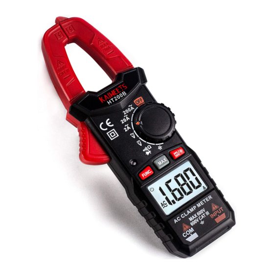
Product Overview ① ① Current Sensing Clamp ② Trigger ③ Rotary Function Switch ② ④ LED Indicator ③ ⑤ Function Buttons ④ ⑥ LED Display Screen ⑤ ⑦ COM Terminal ⑥ (Black test lead) ⑧ INPUT Terminal ⑦ (Red test lead) Black cable Red cable... -
Page 7: Safety-Explanation
Safety-Explanation Hazardous Voltage. Danger! Alternating Current (AC) Direct current (DC) AC and DC Important Information Earth Ground Low Battery Indication Fuse Double Insulated Conforms to requirements of European Free Trade Do not dispose of this product in unsorted municipal waste. IEC Measurement Category III: CAT III equipment has protection against transients CAT.II I I in equipment in fixed-equipment installations, such as distribution panels, feeders... -
Page 8: Function Buttons
Function Buttons Press the “MAX” button to display the maximum value. Press and hold the button for more than 2 seconds to exit “MAX” mode. HOLD: The HOLD function holds the currently displayed measured value on the display so that it can be read or logged in peace. Press this button to turn on or off data hold. -
Page 9: Operating Instructions
Operating Instructions Insert and replace batteries Replace the batteries immediately when the symbol appears in the display. Disconnect the meter from the power source. Remove the test leads from the measuring device, loosen the screws on the back and remove the lower half of the housing, replace the old batteries and screw the cover back on. -
Page 10: Automatic Shutdown
Automatic shutdown No operation in 15 minutes, the clamp meter beeps 3 times. Without further operation, the clamp meter beeps again and switches off automatically. Press any key to restore the clamp meter to operating status. The symbol appears on the display. To deactivate the automatic switch-off, hold down the "FUNC."... -
Page 11: Measurement Operation
Measurement operation AC current measurement The current is measured via the current clamp (1). The sensors in the current clamp detect the magnetic field created by current-carrying conductors. You can take measurements on insulated and not insulated conductors. The test leads should be disconnected from the measuring device when measuring current. Proceed as follows to measure the current: 1) Estimate the current range (2 , 20 or 200 ) and turn the knob to 2 , 20 or 200 . - Page 12 Attention ► Do not use the current clamp to surround more than one conductor. ► If the supply and return conductors (e.g. L and N) are measured, the currents will cancel each other out and no measurement will be displayed. The cables of household appliances usually contain L and N conductors.
-
Page 13: Ac/Dc Voltage Measurement
AC/DC voltage measurement Voltage above 600 V cannot be measured! When measuring high voltage, pay special attention to safety to avoid electric shock or injury. 1) Turn the knob to (DC Voltage) or (AC Voltage) 2) Plug the black test lead into the COM socket and the red test lead into the INPUT socket. 3) Then bring the test probes into contact with the points to be measured. -
Page 14: Resistance Measurement Ω
Resistance measurement Ω Do not enter a voltage above 10 V! Make sure that the power supply to the circuit is disconnected and all capacitors are discharged. 1. Turn the rotary function switch to for resistance measurement. It displays "MΩ” on screen. 2. -
Page 15: Continuity Test
Continuity test Do not enter a voltage above 10 V! Make sure that the power supply to the circuit is disconnected and all capacitors are discharged. 1. Turn the rotary switch to and press the "FUNC." key several times until appears on the display. -
Page 16: Diode Test
Diode Test Do not enter a voltage above 10 V! Make sure that the power supply to the circuit is disconnected and all capacitors are discharged. 1. Turn the rotary function switch to . Press the "FUNC." key 2 times until appears on the display. -
Page 17: Capacitance Measurement
Capacitance measurement 1) Turn the knob to . 2) Insert the red probe in INPUT socket, insert the black probe in COM socket. 3) Contact the probe to the capacitance. 4) Read the measurement result on the screen. Attention When measuring capacitance on the line, disconnect the power supply and discharge all the high-voltage capacitors. -
Page 18: Specification
Specification Display .........................2000 counters Measuring impedance .....................10 MΩ (V range) Operating voltage .......................2 × AAA (1.5V) Weight:..........................approx. 240g Dimension:....................180mm × 100mm × 136mm Security standard: ................IEC 61010-1, IEC 61010-2-032 IEC 61010-031 CATIII 600V Pollution level.............................2 Operating temperature.......................0 to +40 ℃ Operating humidity ........................<80% Operating height ....................0 to max. -
Page 19: Accuracy
Accuracy Function Range Resolution Accuracy DC Volts 200mV/2V/20V200V/600V 0.1mV/0.001V/0.01V/0.1V/1V ±(0.5%+5) AC Volts. 2V/20V/200V/600V 0.001V/0.01V/0.1V/1V ±(1.0%+5) 2A/20A/200A 0.001A/0.01A/0.1A ±(2.5%+8) AC-Amps 0.1Ω/0.001kΩ/0.01kΩ/0.1kΩ/ Resistance 200Ω/2kΩ/20kΩ/200kΩ/2MΩ/20MΩ. ±(1.0%+5) 0.001MΩ/0.01MΩ 0.001nF/0.01nF/0.1nF/0.001uF/ 2nF/20nF/200nF/2uF/20uF/200uF/ Capacitance ±(4.0%+5) 0.01uF/0.1uF0.001mF 2mF. -
Page 20: Maintenance
Maintenance Warning • To avoid electrical shock, disconnect test leads from the Meter before removing its back cover. Never use the Meter with the back cover removed. • Repairs or servicing not covered in this manual should be performed only by qualified personnel. Caution •... -
Page 21: Three Year Warranty
Three Year Warranty KAIWEETS will repair, without charge, any defects due to faulty materials or workmanship for three years from the date of purchase provided that: • Proof of purchase is produced. • Service/repairs have not been attempted by unauthorized persons;...
Need help?
Do you have a question about the HT200B and is the answer not in the manual?
Questions and answers