Advertisement
- 1 Introduction
- 2 Product Overview
- 3 Safety-Explanation
- 4 Function Buttons
- 5 Other Functions
- 6 Operating Instructions
- 7 Making Measurements
- 8 Capacitance measurement
- 9 Diode Test
- 10 Temperature measurement
- 11 Non-contact AC Voltage Detection (NCV)
- 12 Specification
- 13 Accuracy
- 14 Maintenance
- 15 Safety Information
- 16 Documents / Resources
Introduction
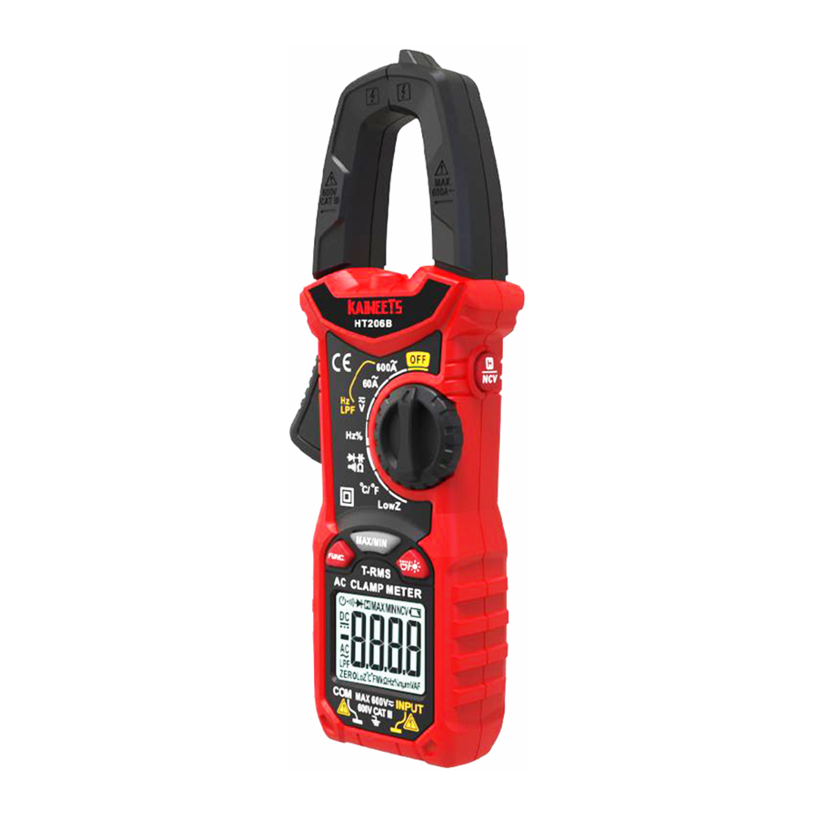
KAIWEETS HT206B is a digital True-RMS clamp meter with automatic range selection.
The Low Impedance (Low-Z) mode can detect and eliminate ghost or stray voltages.
Product Overview

- NCV Probe
- Current Sensing Clamp
- Flashlight
- Data Hold Switch/ NCV Button
- Rotary Function Switch
- Current Clamp Opening Trigger
- Function Buttons
- LED Display Screen
- COM Terminal (black test lead)
- INPUT Terminal (red test lead)
Safety-Explanation

Function Buttons


Other Functions
AC voltage measurement with low-pass filter "LPF"
The "LPF" function allows the clamp meter to filter interfering signals of over 60 Hz. These signals can lead to inaccurate measurements. The meter filters these signals and only measures the voltage signal.

Measurement with LPF:
Set the rotary switch to 600A, 60A or V.
Press the "FUNC." button three times until appears on the display.
Now you can connect test leads and start measurement.
 The LPF function is only possible in AC measurement mode.
High-Impedance Voltage Measurement
High Impedance means high electrical Impedance. This is used to denote the input Impedance or output Impedance of electrical circuits and devices in particular. When measuring in the circuit, this has only a minor impact on the performance of the circuit, particularly in the case of sensitive electronic circuits or control circuits.
Low impedance voltage measurement (LowZ)
LowZ mode allows you to measure AC voltages with a low impedance (approx. 300 kΩ).
In this mode, the multimeter lowers the internal resistance to prevent 'phantom' voltage readings.
As a result, the circuit is more heavily loaded than in the standard measuring mode.
Set the rotary switch to "LowZ" to use the function.
The LowZ voltage measurement must not exceed 600 V.
Due to the reduced impedance, this measurement function is not suitable for continuous measurement. A max. The measurement duration of 1 minute must be observed.
Operating Instructions
Insert and replace batteries
Replace the batteries immediately when the symbol ![]() appears in the display. Disconnect the meter from the power source. Remove the test leads from the measuring device, loosen the screws on the back and remove the lower half of the housing, replace the old batteries and screw the cover back on.
appears in the display. Disconnect the meter from the power source. Remove the test leads from the measuring device, loosen the screws on the back and remove the lower half of the housing, replace the old batteries and screw the cover back on.

Turn on/off the meter
The device is switched on when the rotary switch (5) is set to a measuring function. When the rotary switch is set to OFF, the measuring device is switched off.
Automatic shutdown
No operation in 15 minutes, the clamp meter beeps 3 times. Without further operation, the clamp meter beeps again and switches off automatically.
Press any key to restore the clamp meter to operating status. The symbol appears on the display.
To deactivate the automatic switch-off, hold down the "FUNC." key for more than 2 seconds and switch on the clamp meter at the same time. The symbol ![]() disappears. Restart after switching off the meter, the automatic switch-off can be restored.
disappears. Restart after switching off the meter, the automatic switch-off can be restored.
Auto-ranging
The meter automatically selects the measuring range that is best suited for the measurement performed. The measuring unit and resolution are adjusted at the same time.
AC Zero Input Behavior of True-rms Meters
Unlike averaging meters, which can accurately measure only pure sinewaves, True-rms meters accurately measure distorted waveforms. Calculating True-rms converters require a certain level of input voltage to make a measurement. This is why ac voltage and current ranges are specified from 5% of range to 100% of range. Non-zero digits that are displayed on a True-rms meter when the test leads are open or are shorted are normal. They do not affect the specified ac accuracy above 5% of range.
Connecting Test Leads
Do not test if leads are improperly seated. Results could cause intermittent display readings. To ensure proper connection, firmly press leads into the input jack completely.

Making Measurements
AC current measurement
The current is measured via the current clamp (2). The sensors in the current clamp detect the magnetic field created by current-carrying conductors. You can take measurements on insulated and not insulated conductors.
The test leads should be disconnected from the measuring device when measuring current. Proceed as follows to measure the current:
- Turn the knob to
![]() and select Proper range(6/60A or 600A).
and select Proper range(6/60A or 600A). - Press the clamp release lever and open the clamp.
- Grasp the individual current conductor to be measured and close the current clamp again. The measured conductor must be placed in the center of the clamp, otherwise additional errors will occur.
Attention
- Do not use the current clamp to surround more than one conductor.
- If the supply and return conductors (e.g. L and N) are measured, the currents will cancel each other out and no measurement will be displayed. The cables of household appliances usually contain L and N conductors. A cable separator is required to measure with the current probe.
- If several supply conductors (e.g. L1 and L2) are measured, the currents add up.
- Center the conductor through the current clamp (above the markings)
- Hold your fingers behind the tactile barrier.


- The measured current is shown on the display. If current> 3A, the orange display lights up.
- During AC current measurement, press "FUNC." to display the frequency value or the LPF function measurement.
Voltage Measurement V (DC / AC)
Voltage above 600 V cannot be measured! When measuring high voltage, pay special attention to safety to avoid electric shock or injury.
- Set the rotary switch to
![]() , Press the "FUNC." key to change the AC or DC voltage measurement.
, Press the "FUNC." key to change the AC or DC voltage measurement. - Plug the black test lead into the COM socket and the red test lead into the INPUT socket.
- Then bring the test probes into contact with the points to be measured.
- Read the result on the display. If the voltage is> 80 V, the orange display lights up.
- When measuring the AC voltage, press "FUNC." to display the frequency result or the result of the LPF function.
- If you are measuring low impedance, turn the rotary switch to the Low-Z position and press the "FUNC." button to switch between AC and DC voltage.
")
")
Attention
High impedance voltage measurement: 10 MΩ
Low impedance voltage measurement: 300 kΩ
Frequency or Duty Cycle Measurements (Hz%)
Do not enter a voltage above 10 V!
When measuring high voltage, pay special attention to safety to avoid electric shock or injury.
- Turn the rotary function switch to Hz% and press the "FUNC." key to switch over the frequency or duty cycle measurement.
- Plug the black test lead into the COM socket and the red test lead into the INPUT socket.
- Connect the probes to the measuring points (connect to the measured power supply or to the parallel connection).
- Read the result on the display.
")
")
Resistance measurement Ω
Do not enter a voltage above 10 V! Make sure that the power supply to the circuit is disconnected and all capacitors are discharged.
- Turn the rotary function switch to
![]() for resistance measurement. It displays "MΩ" on screen.
for resistance measurement. It displays "MΩ" on screen. - Turn off the circuit under test.
- Plug the black test lead into the COM socket and the red test lead into the INPUT socket.
- Then place the test probes in contact with the points at which the resistance must be measured.
- Read the result on the display.


Note: When measuring resistance on a circuit, the measured value can be influenced by other circuits.
Continuity test ![]()
Do not enter a voltage above 10 V! Make sure that the power supply to the circuit is disconnected and all capacitors are discharged.
- Turn the rotary switch to
![]() and press the "FUNC." key several times until appears
and press the "FUNC." key several times until appears ![]() on the display.
on the display.
The endurance test is now active. - Plug the red test lead into the INPUT socket and the black test lead into the COM socket.
- Connect the probes to the circuit or component under test.
- If the resistance is <30 Ω, an acoustic signal sounds continuously and the orange backlight lights up.
Note: When measuring resistance on a circuit, the measured value can be influenced by other circuits.

Capacitance measurement
- Remove power from the circuit being tested. Turn the rotary function switch to
![]() ,press the "FUNC." key to cycle through from resistance to continuity to capacitance function.
,press the "FUNC." key to cycle through from resistance to continuity to capacitance function. - Connect the black test lead to the COM terminal and the red test lead to the INPUT terminal.
- Connect the probes across the circuit or (capacitance) component to be tested.
- View the reading on the display.

To avoid electrical shock when testing capacitance in a circuit, make sure the power to the circuit is turned off and all capacitors are discharged.
To avoid damaging the instrument or equipment, do not input a voltage greater than 10V.
Note: When measuring capacitance greater than 100uF, it will take a long to measure correctly.
Diode Test
- Turn the rotary function switch to
![]() Press the "FUNC." key to cycle through from resistance (to continuity to capacitance) to diode function.
Press the "FUNC." key to cycle through from resistance (to continuity to capacitance) to diode function. - Remove power from the circuit being tested.
- Connect the black test lead to the COM terminal and the red test lead to the INPUT terminal.
- Connect the black test lead to the cathode side and the red test lead to the anode side of the diode being tested.
- Read forward bias voltage value on the LCD.6
- If the polarity of the test leads is the reverse of the diode polarity, the LCD reading shows " OL". This can be used for distinguishing the anode side and cathode side of a diode.


To avoid electrical shock when testing diodes in a circuit, make sure the power to the circuit is turned off and all capacitors are discharged.
To avoid damaging the instrument or equipment, do not input a voltage greater than 10V.
Temperature measurement
- Turn the rotary function switch to ℃/℉ position. Press "FUNC." to select °C or °F, the display reflects the chosen temperature unit.
- Insert the K-type thermocouple into the meter, the positive pole (red) of the thermocouple into the INPUT input and the negative pole (black) into the COM input.
- Contact the thermocouple probe with the measurement object, then the reading appears on the display.
- Connect the temperature probe with the testing point.
To avoid possible electric shock DO NOT apply the probe tip to any conductor that is greater than 30 V ac, 42 V peak or 60 V dc to earth.
Note:
It takes a long time for the cold end of thermocouple to be restored in the instrument to achieve thermal balance with the environment.

Non-contact AC Voltage Detection (NCV)
Make sure that all measuring sockets are free. Remove all test leads and adapters from the meter.
This function only serves as an aid.
Before making contact measurements, you should make sure that there is no voltage.
- At any position, hold down the for more than 2 seconds, "click" a sound, the instrument shows the "NCV" character and then enter the NCV detection function.
- Then the NCV probe will be approached the detected point gradually.
- When the signal of weak electromagnetic field is sensed, the character "- - L" is displayed and there appears slow beeping sound.
- When the signal of strong electromagnetic field is sensed, the character "- - H" is displayed, the buzzer emits a quick beep sound, and the orange LED indicator light is on
- Press more than 2 seconds or turn the rotary function to exit NCV detection function.
Specification
| Display | 6000 counters, True RMS |
| Display update frequency | approx. 3 Hz |
| Measuring impedance | 10 MΩ (V range) |
| Operating voltage | 2 × AAA (1.5V) |
| Weight | approx. 260g |
| Dimension | 193mm × 73mm × 34mm |
| Security standard | EN61010-1, -2-030 EN61010-2-033 EN61326-1 CATIII 600V |
| Operating temperature | 0 to +40 ℃ |
| Operating humidity | <80% (> 30 ℃) |
| Operating height | 0 to max. 2000 m |
| Storage temperature | - 10 to +60 ℃ |
| Air humidity in storage | <70% |
Accuracy

Maintenance
- To avoid electrical shock, disconnect test leads from the Meter before removing its back cover.
Never use the Meter with the back cover removed. - Repairs or servicing not covered in this manual should be performed only by qualified personnel.

- To avoid contamination or static damage, do not touch the circuit board without proper static protection.
- If the Meter is not going to be used for a long time, remove the battery. Do not store the Meter in a high temperature or a high humidity environment.
Cleaning the Meter
- To avoid damaging the meter, do not use abrasives or solvents on this instrument.
- Periodically clean the Meter by wiping it with a damp cloth and mild detergent.
- Do not get water inside the case. This may lead to electrical shock or damage to the instrument.
- Wipe the contacts in the socket with a clean cotton swab soaked in alcohol.
Safety Information
Read First
To avoid possible electric shock or personal injury, please obey the following instructions:
- Use the Meter only as specified in this manual or the protection provided by the Meter might be impaired.
- Avoid working alone so assistance can be rendered.
- Never measure AC current while the test leads are inserted into the input jacks.
- Do not use the Meter in wet or dirty environments.
- Inspect the test leads before use. Do not use them if insulation is damaged or metal is exposed.
- Check the test leads for continuity. Replace damaged test leads before using.
- Use extreme caution when working around bare conductors or bus bars. Contact with the conductor could result in electric shock.
- Do not hold the Meter anywhere beyond the tactile barrier.
- When measuring current, center the conductor in the clamp.
- Do not apply more than the rated voltage, as marked on the Meter, between the terminals or between any terminal and earth ground.
- Remove test leads from the Meter before opening the Meter case.
- Never operate the Meter with the back cover removed or the case open.
- Never remove the back cover or open the case of an instrument without first removing the test leads or the jaws from a live conductor.
- Use caution when working with voltages above 30 V ac RMS, 42 V ac peak, or 60 V dc. These voltages pose a shock hazard.
- Do not attempt to measure any voltage that might exceed the maximum range of the Meter- 600 V RMS and 1 kHz.
- Do not operate the Meter around explosive gas, vapor, or dust.
- When using probes, keep fingers behind the finger guards.
- When making electrical connections, connect the common test lead before connecting the live test lead; when disconnecting, disconnect the live test lead before disconnecting the common test lead.
- Disconnect circuit power and discharge all high-voltage capacitors before testing resistance, continuity, or diodes.
- Check the operation of the meter at a known source before and after use.

Documents / ResourcesDownload manual
Here you can download full pdf version of manual, it may contain additional safety instructions, warranty information, FCC rules, etc.
Download KAIWEETS HT206B - True-RMS Digital Clamp Meter Manual
Advertisement


Need help?
Do you have a question about the HT206B and is the answer not in the manual?
Questions and answers