
Subscribe to Our Youtube Channel
Related Manuals for Kaiweets HT208D


Summary of Contents for Kaiweets HT208D
- Page 1 True-rms Digital Clamp Meter HT208D User Manual Cont act us: support @Kai weet s.co m...
-
Page 2: Table Of Contents
Contents Introduction ��������������������������������������������������������������������������������������������������������������������� 1 Safety information��������������������������������������������������������������������������������������������������������� 1 Product Overview ����������������������������������������������������������������������������������������������������������� 3 Symbol-Explanation ������������������������������������������������������������������������������������������������������� 4 Function Buttons ������������������������������������������������������������������������������������������������������������ 5 Advanced Functions ������������������������������������������������������������������������������������������������������ 7 AC current measurement with “Inrush” function ����������������������������������������������������������� 7 AC current measurement with “VFD” function �������������������������������������������������������������� 8 AC voltage measurement with “VFD” function�������������������������������������������������������������� 8 High-Impedance voltage measurement������������������������������������������������������������������������... - Page 3 Insert and replace the batteries ���������������������������������������������������������������������������������� 10 Turn on/off the meter �������������������������������������������������������������������������������������������������� 10 Automatic shutdown ��������������������������������������������������������������������������������������������������� 10 Auto-ranging ��������������������������������������������������������������������������������������������������������������� 11 AC zero input behavior of True-rms meters ���������������������������������������������������������������� 11 Connecting test leads ������������������������������������������������������������������������������������������������� 12 Making Measurements ������������������������������������������������������������������������������������������������� 12 AC/DC current measurement ������������������������������������������������������������������������������������� 12 AC/DC voltage measurement �������������������������������������������������������������������������������������...
- Page 4 Capacitance measurement����������������������������������������������������������������������������������������� 20 Temperature measurement ���������������������������������������������������������������������������������������� 21 Non-contact AC voltage detection (NCV) ������������������������������������������������������������������� 22 Live detection ������������������������������������������������������������������������������������������������������������� 22 Specification ����������������������������������������������������������������������������������������������������������������� 24 Accuracy ��������������������������������������������������������������������������������������������������������������������� 25 Maintenance ������������������������������������������������������������������������������������������������������������������ 27 Cleaning the meter ����������������������������������������������������������������������������������������������������� 27 Three Year Warranty ����������������������������������������������������������������������������������������������������� 28...
- Page 6 terminals or between any terminal and earth ground� • Remove test leads from the Meter before opening the Meter case� • Never operate the Meter with the back cover removed or the case open� • Never remove the back cover or open the case of an instrument without first removing the test leads or the jaws from a live conductor�...
-
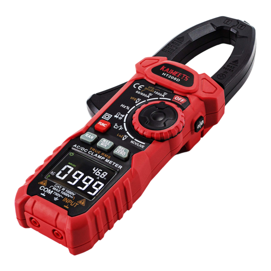
Page 7: Product Overview
Product Overview ① NCV Probe ② Current Sensing Jaw ③ Flashlight ④ Tactile Barrier ⑤ Rotary Function Switch ⑥ Function Buttons ⑦ Display ⑧ Alignment Marks ⑨ Jaw Release ⑩ INPUT Terminal (red test lead) ⑪ COM Terminal (black test lead) ⑫... -
Page 8: Symbol-Explanation
Symbol-Explanation Hazardous Voltage� Danger! Alternating Current (AC) AC and DC Direct current (DC) Important Information Earth Fuse Low Battery Indication Double Insulated Conforms to European Union directives� Do not dispose of this product as unsorted municipal waste� IEC Measurement Category III: CAT�III equipment has protection against CAT. -
Page 9: Function Buttons
Function Buttons Press the “FUNC�” key to switch the respective secondary function between the different measurements for the applications accessible via the function switch such as between AC and DC� Auto-Ranging by default� Switches to manual mode and cycles through all ranges� Auto-Ranging restored when pressed for two seconds�... - Page 10 NOTE: In DC current measurement mode, this key is the “ZERO”key� However, in other functions, this key is the “REL” key� “REL” Function: Relative (REL) mode: Stores existing reading (a delta) and resets display to zero� Sets a relative reference point tomeasure against the next reading�...
-
Page 11: Advanced Functions
Advanced Functions AC current measurement with “Inrush” function Inrush current is the instantaneous high input Current Peak current current drawn by a power supply or electrical equipment at turn-on� This arises due to the Inrush current magnitude high initial currents required to charge the capacitors and inductors or transformers�... -
Page 12: Ac Current Measurement With "Vfd" Function
When an electrical device is first powered on, inrush current is the surge or momentary burst of current that flows into it. AC current measurement with “VFD” function (Variable Frequency Drive Filtering) The VFD mode eliminates high frequency noise in voltage measurements by means of a low-pass filter�... -
Page 13: High-Impedance Voltage Measurement
current, which may exceed the indicated value� High-Impedance voltage measurement High Impedance means high electrical Impedance� This is used to denote the input Impedance or output Impedance of electrical circuits and devices in particular� When measuring in the circuit, this has only a minor impact on the performance of the circuit, particularly in the case of sensitive electronic circuits or control circuits�... -
Page 14: Operating Instructions
Operating Instructions Insert and replace the batteries Replace the batteries immediately when the symbol appears in the display� Disconnect the meter from the power source� Remove the test leads from the measuring device, loosen the screws on the back and remove the lower half of the housing, replace the old batteries and screw the cover back on�... -
Page 15: Auto-Ranging
the clamp meter beeps again and switches off automatically. Press any key to restore the clamp meter to operating status� The symbol appears on the display� To deactivate the automatic switch-off, hold down the “FUNC.” key for more than 2 seconds and switch on the clamp meter at the same time�... -
Page 16: Connecting Test Leads
Connecting test leads Do not test if leads are improperly seated� INCORRECT Results could cause intermittent display readings� To ensure proper connection, firmly press leads into the jack completely. CORRECT Making Measurements AC/ DC current measurement • When making current measurements, disconnect the test leads from the Meter� •... - Page 17 inside the Jaw� 1� Turn the rotary switch to the correct current setting (60/600 , 1000 )� “DC” appears on the display� Press the “FUNC�” button, AC is shown on the display� 2� If measuring DC current, wait for the display to stabilize and then push to zero the Meter�...
-
Page 18: Ac/Dc Voltage Measurement
AC/DC voltage measurement Voltage above 750 V(AC)/1000V (DC) cannot be measured! When measuring high voltage, pay special attention to safety to avoid electric shock or injury� 1� Set the rotary switch to , press the “FUNC�” key to change the AC or DC... - Page 19 voltage measurement� 2� Plug the black test lead into the COM socket and the red test lead into the INPUT socket� 3� Then bring the test probes into contact with the points to be measured� 4� Read the measurement results on the display� Attention ▶...
-
Page 20: Frequency Or Duty Cycle Measurements (Hz%)
Frequency or duty cycle measurements (Hz%) 1� Turn the rotary function switch to Hz%� 2� Plug the black test lead into the COM socket and the red test lead into the INPUT socket� 3� Connect the probes to the measuring points (connect to the measured power supply or to the parallel connection)�... -
Page 21: Resistance Measurement Ω
Resistance measurement Ω 1. Turn the rotary function switch to for resistance measurement. It displays “MΩ” on screen� 2. Turn off the circuit under test. 3� Plug the black test lead into the COM socket and the red test lead into the INPUT socket�... -
Page 22: Continuity Test
Continuity test 1� Turn the rotary switch to and press the “FUNC�” key until appears on the display� The continuity test is now active� 2� Plug the black test lead into the COM socket and the red test lead into the INPUT socket�... -
Page 23: Diode Test
Diode test 1� Turn the rotary function switch to , press the press the “FUNC�” key 2 times until appears on the display� 2� Remove power from the circuit being tested� 3� Connect the black test lead to the COM terminal and the red test lead to the INPUT terminal�... -
Page 24: Capacitance Measurement
Capacitance measurement 1� Remove power from the circuit being tested� Turn the rotary function switch to press the “FUNC�” key 3 times until “nf” appears on the display� 2� Connect the black test lead to the COM terminal and the red test lead to the INPUT terminal�... -
Page 25: Temperature Measurement
Temperature measurement 1� Turn the rotary function switch to ℃ / ℉ position� 2� Insert the K-type thermocouple into the meter, the positive pole (red) of the thermocouple into the INPUT input and the negative pole (black) into the COM input� 3�... -
Page 26: Non-Contact Ac Voltage Detection (Ncv)
Non-contact AC voltage detection (NCV) When using NCV function, please remove the probe, otherwise the detection sensitivity will be affected. 1� Turn the knob to , the “ ” symbol is displayed� 2� Then the NCV probe will be approached the detected point gradually� 3�... - Page 27 4� When the signal of weak electromagnetic field is sensed, the character “- - L” is displayed, the buzzer emits a slow beep sound and the green LED indicator light is on� 5. When the signal of strong electromagnetic field is sensed, the character “- - H” is displayed, the buzzer emits a quick beep sound and the red LED indicator light is on�...
-
Page 28: Specification
Specification Display ������������������������������������������������������������������������������������������ 6000 counters, True RMS Display update frequency ����������������������������������������������������������������������������������approx� 3 Hz Measuring impedance ................10 MΩ (V range) Operating voltage ������������������������������������������������������������������������������������������� 3 × AAA (1�5V) Weight:���������������������������������������������������������������������������������������������������������������� approx� 700g Dimension:����������������������������������������������������������������������������������� 285mm × 135mm × 60mm Security standard: ���������������������������������������������������������������������������������������������� IEC 61010-1 IEC 61010-2-032: CAT III 1000V / CAT IV 600V IEC 61010-2-033: CAT III 1000V / CAT IV 600V Pollution level���������������������������������������������������������������������������������������������������������������������������2... -
Page 29: Accuracy
Accuracy Function Range Resolution Accuracy 600mV/6V/60V/600V 0�1mV/0�001V/0�01V/0�1V ±(0�5%+5) DC Volts 1000V ±(0�8%+5) 600mV/6V/60V/600V 0�1mV/0�001V/0�01V/0�1V ±(0�8%+5) AC Volts 750V ±(1�0%+5) VFD(750V) 0�1V ±(2�0%+5) DC Amps 60A/600A/1000A 0�01A/0�1A/1A ±(2�5%+8) ±(2�5%+8) AC Amps 60A/600A/1000A 00�01A/0�1A/1A VFD:±(5�0%+10) INRUSH:±(5�0%+10) - Page 30 600Ω/6kΩ/60kΩ/600kΩ/ 0.1Ω/0.001kΩ/0.01kΩ/0.1kΩ/ Resistance ±(1�0%+5) 6MΩ/60MΩ 0.001MΩ/0.01MΩ 10nf/100nf/1000nf/10uf/ 0�001nf/0�01nf/0�1nf/0�001uf/ ±(4�0%+5) 100uf/1000uf/10mf 0�01uf/0�1uf/0�001mf Capacitance 100mf 0.01mf ±(5.0%+10) 10Hz/100Hz/1000Hz/10 0.001Hz/0.01Hz/0.1Hz/0.001kHz/ ±(1.0%+3) kHz/100kHz/1000kHz 0.01kHz/0.1kHz Frequency 10MHz 0.001MHz ±(3.0%+3) Duty Cycle 1%~99% 0.1% ±(3.0%+3) -20℃ ~ 0℃ 1℃ ±3℃ 0℃ ~ 400℃ ±1.0% or ± 2℃ 400℃...
-
Page 31: Maintenance
Maintenance Warning • To avoid electrical shock, disconnect test leads from the Meter before removing its back cover� Never use the Meter with the back cover removed� • Repairs or servicing not covered in this manual should be performed only by qualified personnel�... -
Page 32: Three Year Warranty
Three Year Warranty KAIWEETS will repair, without charge, any defects due to faulty materials or workman- ship for three years from the date of purchase provided that: • Proof of purchase is produced� • Service/repairs have not been attempted by unauthorized persons;...
Need help?
Do you have a question about the HT208D and is the answer not in the manual?
Questions and answers