Table of Contents
Advertisement
Advertisement
Table of Contents

Related Manuals for Kaiweets HT112B


Summary of Contents for Kaiweets HT112B
- Page 1 TRUE RMS 6000 COUNTS DIGITAL MULTIMETER HT112B Contact us: support@Kaiweets.com...
-
Page 2: Table Of Contents
Contents Safety Instructions ..........1 Safety Operation ............1 Safety Symbols ............2 Install The Battery Or Fuse .........3 Install Battery ..............3 Replace Fuse .............4 Overview ..............5 Meter Panel ..............5 Auto Power Off ............6 Measurement Operation ........6 Smart Measurement ........6 DC/AC mV Measurement ..........9 Frequency/Duty Measurement ........10 Capacitance Measurement ........10 Diode Test ..............11... -
Page 3: Safety Instructions
Safety Instructions This meter conforms to the IEC61010-1 international electrical safety standard. The design and manufacture of instruments shall strictly comply with IEC61010-1 CATIII 600V safety standard and pollution level 2. Safety Operation WARNING To avoid possible electric shock or personal injury and other safety accidents, please abide by the following specifications: ●... -
Page 4: Safety Symbols
● Do not work alone so that you can get help in an emergency. ● To avoid electric shock or injury due to wrong reading, please replace the batteries in time when the indicator “ ”is displayed. ● Do not use the instrument around explosive gas or steam or in a humid environment. -
Page 5: Install The Battery Or Fuse
Suitable for testing and measuring circuits connected to the distribution part of low voltage power supply devices in buildings. Install The Battery Or Fuse Install Battery ① Remove the rubber sleeve on the outside of the multimeter. ② Remove the screw that secures the battery cover and remove the battery cover. -
Page 6: Replace Fuse
WARNING ● In order to avoid electric shock or personal injury caused by inaccurate reading, please replace batteries immediately when the battery power is low. ● Do not discharge the battery by shorting it or reversing its polarity. ● In order to ensure the safe operation and maintenance of the meter, please take out the battery when it is not used for a long time. -
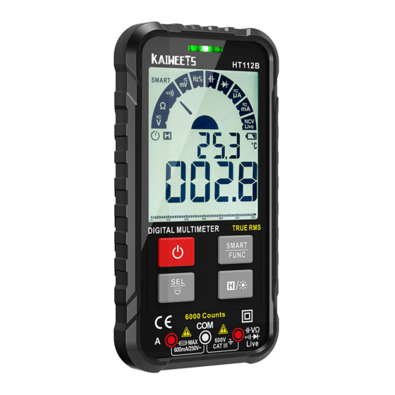
Page 7: Overview
Overview METER PANEL ⑦ ① ⑧ ② ③ ④ ⑤ ⑥ ① Indicator light ② Display ③ Keys Power key Long press to turn on/off. Smart/Manual Mode Key After the meter is powered on, it defaults to a smart ● function. -
Page 8: Auto Power Off
Backlight / Data hold key Press this key to turn on or off the data holding function, ”H” ● will be displayed on the screen. Press this key for more than 2 seconds to turn on or off the ● backlight. - Page 9 measurement. “ ” will be displayed. 2) Insert the red probe into the “ ” jack and the black probe into the “COM” jack. 3) Touch the test lead tips together to check if they are connected normally. The indicator light should turn green and the buzzer sound.
- Page 10 ③ When the resistance is greater than 50Ω, it will automatically jump to resistance measurement. ④ If the measured value is equal to the nominal resistance of the resistor or within the range of error, the resistor is functioning correctly. If there is a large deviation between the nominal resistance and the measured resistance, the resistor is bad.
-
Page 11: Dc/Ac Mv Measurement
DC/AC mV Measurement 1) Long press “ ” key to turn on the power. 2) Insert the red probe into the “ ” jack and the black probe into the “COM” jack. 3) Touch the test lead tips together to check if they are connected normally. -
Page 12: Frequency/Duty Measurement
Frequency/Duty Measurement 1) Long press “ ” key to turn on the power. 2) Insert the red probe into the “ ” jack and the black probe into the “COM” jack. 3) Touch the test lead tips together to check if they are connected normally. -
Page 13: Diode Test
3) Touch the test lead tips together to check if they are connected normally. The indicator light should turn green and the buzzer sounds. 4) Press “ ” key to switch to “ ” function. 5) Connect the probe with both ends of the capacitor in parallel for measurement. -
Page 14: Dc/Ac Current Measurement
to the opposite ends of the diode and measure again. 6) After the reading stabilizes, record the reading from the screen. 7) When the measurement is completed, disconnect the test leads from the measured object. WARNING To avoid damage to the meter and/ or the measured object, disconnect the circuit power and discharge all the high-voltage capacitors before testing. -
Page 15: Non-Contact Voltage (Ncv)
6) After the reading stabilizes, record the reading from the screen. When measuring AC current, the frequency is displayed at the same time. 7) When the measurement is completed, disconnect the test leads from the measured object. WARNING 1. Pay special attention to safety when measuring high voltage to prevent safety hazard. -
Page 16: Live Test
H”. In general, the wire detected is the live at this time. Customized Matching Meter Pen This product uses customized test leads, you can go to the KAIWEETS Amazon store to buy the matching test leads set. Specifications ● Environmental conditions: CAT. III 600V ●... -
Page 17: Accuracy
● Low battery: “ ” displayed ● Polarity indication: “-” displayed ● Power: 2 x 3V CR2032 batteries Accuracy Accuracy is applicable within one year after calibration. Reference conditions: 18°C to 28°C, < 80% RH. Accuracy: ± (% reading + word) DC voltage Range Resolution... -
Page 18: Dc Current
DC current Range Resolution Accuracy 6000μA 1μA 60mA 0.01mA ±(1.2%+5) 600mA 0.1mA Overload protection: F600mA/250V Fuse Maximum current: 600mA AC current Range Resolution Accuracy 6000μA 1μA 60mA 0.01mA ±(1.5%+5) 600mA 0.1mA Overload protection: F600mA/250V Fuse Maximum current: 600mA Frequency Response: 40Hz ~ 1kHz True RMS Resistance Range Resolution... -
Page 19: Capacitance
Capacitance Range Resolution Accuracy 0.001nF 60nF 0.01nF 600nF 0.1nF ±(4.0%+5) 6μF 0.001μF 60μF 0.01μF 600μF 0.1μF 0.001mF ±(5.0%+5) 60mF 0.01mF Overload protection: 250V Frequency/Duty Range Resolution Accuracy 10Hz 0.001Hz 100Hz 0.01Hz 1000Hz 0.1Hz ±(1.0%+5) 10kHz 0.001kHz 100kHz 0.01kHz 1000kHz 0.1kHz 10MHz 0.001MHz ±(3.0%+5) -
Page 20: Diode
3) Overload protection: 250V μA or mA Position: 1) Range: 10Hz ~ 2 kHz 2) Current response: ≥ 2mA 3) Overload protection: F600mA/250V fuse Diode Open Voltage: shows is an Approx. 2.0V approximation of Overload protection: diode forward voltage 250V Continuity Open Voltage: <Approx.50Ω: the... -
Page 21: Clean
Three years Warranty KAIWEETS will repair, without charge, any defects due to faulty materials or workmanship for three years from the date of purchase provided that: Proof of purchase is produced.
Need help?
Do you have a question about the HT112B and is the answer not in the manual?
Questions and answers