Sign In
Upload
Download
Table of Contents
Contents
Add to my manuals
Delete from my manuals
Share
URL of this page:
HTML Link:
Bookmark this page
Add
Manual will be automatically added to "My Manuals"
Print this page
×
Bookmark added
×
Added to my manuals
Manuals
Brands
Hyster Manuals
Forklifts
F117
Service & repair manual
Hyster F117 Service & Repair Manual
Hide thumbs
1
2
3
Table Of Contents
4
5
6
7
8
9
10
11
12
13
14
15
16
17
18
19
20
21
page
of
21
Go
/
21
Contents
Table of Contents
Bookmarks
Table of Contents
Table of Contents
General
Description and Operation
Hydraulic Oil Supply
Manifold, Section 1 of Hydraulic Plate
Main Control Valve, Section 2 of Hydraulic Plate
Description
Operation
Auxiliary Section
Tilt Section
Lift Section
Return Manifold, Section 3 of Hydraulic Plate
Brake Manifold, Section 4 of Hydraulic Plate
Cooling Circuit
Service Brake
Parking Brake
Flow Amplifier, Section 5 of Hydraulic Plate
Manifold, Section 1 of Hydraulic Plate
General
Valves and Pressure Switches
Main Control Valve, Section 2 of Hydraulic Plate
Remove
Disassemble
Auxiliary Section
Lift Section
Lift/Tilt Section
Clean and Inspect
Assemble
Auxiliary Section
Lift Section
Lift/Tilt Section
Install
Advertisement
Quick Links
1
Table of Contents
2
General
3
Hydraulic Oil Supply
4
Description and Operation
5
Operation
6
General
Download this manual
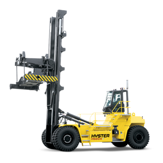
Hyster F117 (H1050HD-CH, H1150HD-CH) Forklift
Table of
Contents
Previous
Page
Next
Page
1
2
3
4
5
Advertisement
Table of Contents
Need help?
Do you have a question about the F117 and is the answer not in the manual?
Ask a question
Questions and answers
Related Manuals for Hyster F117
Forklifts Hyster H40.00-48.00XM-12 Assembly Manual
(17 pages)
Lifting Systems Hyster H40.00-52.00XM-16CH Periodic Maintenance Procedure
(10 pages)
Forklifts Hyster F108 Service & Repair Manual
(21 pages)
Forklifts Hyster J2.00XM Safety Precautions Maintenance And Repair
Instrument cluster (26 pages)
Forklifts Hyster E50XM Service & Repair Manual
Electric (21 pages)
Forklifts Hyster H8.00-12.00XM Service & Repair Manual
(21 pages)
Forklifts Hyster F160 Service & Repair Manual
(21 pages)
Forklifts Hyster F006 Service & Repair Manual
(22 pages)
Forklifts Hyster H4.0FT5 Service & Repair Manual
(25 pages)
Forklifts Hyster F001 Service & Repair Manual
(38 pages)
Forklifts Hyster S30FT Service Manual
Mast repairs (21 pages)
Forklifts Hyster E004 Service & Repair Manual
(19 pages)
Forklifts Hyster F004 Service & Repair Manual
(21 pages)
Forklifts Hyster F005 Manual
(22 pages)
Forklifts Hyster F003 Service & Repair Manual
(21 pages)
Forklifts Hyster R30XMF3 Instruction Manual
Mast (29 pages)
This manual is also suitable for:
A917
H1050hd-ch
H1150hd-ch
H40.00-48.00xm-12
H800-1050hd
H800-1050hds
...
Show all
H40.00-52.00xm-16ch
Table of Contents
Print
Rename the bookmark
Delete bookmark?
Delete from my manuals?
Login
Sign In
OR
Sign in with Facebook
Sign in with Google
Upload manual
Upload from disk
Upload from URL


Need help?
Do you have a question about the F117 and is the answer not in the manual?
Questions and answers