
Related Manuals for Rice Lake Digi DC-782


Summary of Contents for Rice Lake Digi DC-782
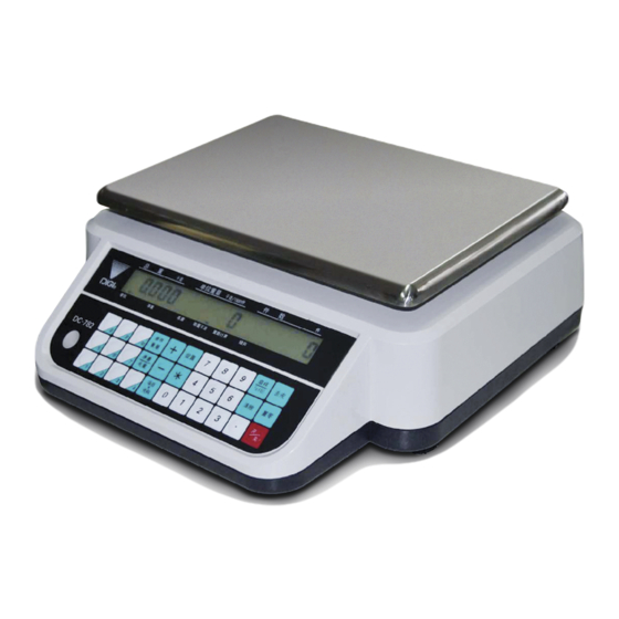
- Page 1 All manuals and user guides at all-guides.com DC-782 Counting Scale Version 1.006 Counting Scale Operation Manual To be the best by every measure 109429...
- Page 2 All manuals and user guides at all-guides.com...
-
Page 3: Table Of Contents
6.2 Program Item Code, Tare Weight, Unit Weight, Setpoint 1 and 2 ......25 © 2012 Rice Lake Weighing Systems. All rights reserved. Printed in the United States of America. - Page 4 All manuals and user guides at all-guides.com 6.3 Program a General Setpoint ............27 6.4 Programming a Preset Key .
-
Page 5: About This Manual
All manuals and user guides at all-guides.com About This Manual This manual contains operating procedures for the DC-782 counting scale and provides the user with all the information necessary for setup and operation. It is organized based on the procedures you will likely follow when setting up and using your counting scale. -
Page 6: Keyboard And Display
All manuals and user guides at all-guides.com Keyboard and Display Figure 1-1 shows the DC-782 console with its indicator lamps, the function keyboard and the numeric keypad. Annunciators are described in Section 1.3.2. Section 1.3.3 describes the DC-782 keyboard and keypad. Figure 1-1. -
Page 7: Key Functions
All manuals and user guides at all-guides.com 1.3.3 Key Functions The DC-782 features many functions for managing inventory information and scale operation. Figure 1-2 shows the key-sheet and Table 1-4 lists the keys and key functions of the DC-782 keyboard. Figure 1-2. - Page 8 All manuals and user guides at all-guides.com Description + (Plus) key. Weighing Mode - Used to accumulate data. Also prompts outputting of data to a PC if one is connected. Programming Mode - Used to navigate to the next specification when programming SPEC codes. MODE key - Used to enter the programming mode from the weighing mode.
-
Page 9: Installation
1. Immediately after unpacking, visually inspect the DC-782 counting scale to ensure all components are included and undamaged. If any were damaged in shipment, notify Rice Lake Weighing Systems and the shipper immediately. 2. The DC-782 counting scale is carefully packed for protection during shipping. After opening the box, remove all the components. -
Page 10: Powering Up The Dc-782
All manuals and user guides at all-guides.com Leveling Bubble Figure 2-1. Leveling Bubble Powering Up the DC-782 The DC-782 can be operated either from an AC power source or with a rechargeable battery pack (DC power). The DC power allows the unit to be completely portable. Instructions for DC operation are contained in Section 2.4.2. -
Page 11: Dc Battery Pack Replacement/Installation
All manuals and user guides at all-guides.com 4. Once the scale is on, the time interval before the scale will automatically power itself off, if there no key is pressed and no weight is placed on the platter, is determined by SPEC 00- Auto Power-Off Function. The default is 0000: Disabled. -
Page 12: Battery Charging
All manuals and user guides at all-guides.com going into the normal weighing mode. • If SPEC 20, Bit 2 is set to 1: Standard, the scale’s display will test the LCD segments for each numeral from 0 to 9, asterisks, decimal points and annunciators before going into the normal weighing mode. -
Page 13: Replacement Parts
All manuals and user guides at all-guides.com Replacement Parts The following list contains the part numbers and descriptions of replacement parts available for the DC-782 counting scale. RLWS Part Number Description 108516 Rechargeable Battery Pack, 6 V, 5.0AH 108517 AC Adapter 110VAC 108518 AC Adapter 230VAC 109429... -
Page 14: Block Diagram Of Electrical Connections
All manuals and user guides at all-guides.com Block Diagram of Electrical Connections The following block diagram illustrates the electrical connections. DC-782 Operation Manual... -
Page 15: Physical Layout Of Electrical Connections
All manuals and user guides at all-guides.com Physical Layout of Electrical Connections The following diagram illustrates the actual layout of the electrical connections. Installation... -
Page 16: Configuration Settings
All manuals and user guides at all-guides.com Configuration Settings This section presents the setup and configuration of the DC-782 counting scale to be used specifically by distributors and service technicians. Configuring these specifications allow you to tailor the DC-782 to your specific applications. - Page 17 All manuals and user guides at all-guides.com If this is the SPEC that you want to modify, enter the new setting from the numeric keypad and press the * CONFIRM key to enter the change into temporary memory and move to the next SPEC code. 2.
-
Page 18: Weight And Measurement Specifications (142 Settings)
All manuals and user guides at all-guides.com SPEC No. Bit 3 Bit 2 Bit 1 Bit 0 Stop bit of RS-232C Data length of RS-232C Parity of RS-232C 0: 1 bit (DEFAULT) 0: 7 bits 00: None (DEFAULT) 1: 2 bit 1: 8 bits (DEFAULT) 01: Odd 10: Even... - Page 19 All manuals and user guides at all-guides.com 3. To change another SPEC code before exiting, repeat Steps 1 and 2. 4. To save all the changed SPEC settings currently in temporary memory and exit to the Weighing Mode, press the TARE key. 5.
- Page 20 All manuals and user guides at all-guides.com SPEC No. Bit 3 Bit 2 Bit 1 Bit 0 Tare Auto Clear Unit Weight Auto Clear Auto Clear Condition Net/Gross Multi-Interval 0: Allow 0: .Allow 0: >=Gross 21e & >=Net 5e 0: Gross 1: Inhibit (DEFAULT) 1: Inhibit (DEFAULT) 1: >=Net 1e &...
-
Page 21: Calibration
All manuals and user guides at all-guides.com Calibration The DC-782 scale is a high-precision instrument. Although the scale needs very little maintenance, you may want to check the calibration after every month or so of normal usage. To do this you will need to have a test weight of approximately the total capacity of the scale (i.e. - Page 22 All manuals and user guides at all-guides.com 3. The scale display will confirm that you are in the Calibration Mode. 4. Make sure that there is no weight on the platform of the scale you are calibrating and press the CONFIRM key.
-
Page 23: Scale Operations
All manuals and user guides at all-guides.com Scale Operations The following sections contain detailed operator instructions for the DC-782 counting scale (see Figure 5-1). Included are instructions on how to enter tare weights, how to enter unit weights, and how to perform counting operations. -
Page 24: One Touch Tare (When The Tare Weight Is Unknown)
The Benefit of Unit Weight per 1000 Pieces Over Unit Weight per 1 Piece Your DIGI DC-782 scale displays the unit weight calculated per 1000 pieces. Why is this a more accurate way to display unit weight than the more common unit weight per individual piece? The scale’s internal microprocessor calculates unit weights to 7 or 8 decimal places. -
Page 25: Unit Weight Operation By Sampling
All manuals and user guides at all-guides.com Example: A sample of 10 zener diodes is placed on the scale. The Unit Weight is computed by the scale to be 0.0006536 lbs. However, the scale has a 5 character display for Unit Weight so the scale can only display.0065 as the Unit Weight. -
Page 26: Operations Without Recalling An Item Code
All manuals and user guides at all-guides.com Operations Without Recalling an Item Code The following sections describe ways to carry out operations without having to recall the Item codes. 5.4.1 A Single Counting Operation - Without Recalling an Item Code At times you may want to perform a weighing and counting operation without recalling an Item Code from memory. - Page 27 All manuals and user guides at all-guides.com 7. Continue with the remainder of the containers to be counted. The total number of parts stored in all the containers will be stored in the accumulation register. 8. To subtract pieces from the accumulation, place the container to be subtracted on the platform and press the - (Minus) key.
-
Page 28: Using Item Codes In Weighing Mode
All manuals and user guides at all-guides.com 4. If at the end of the procedure, if you want to see how many remain in the bin or container, you first have to know the tare weight of the bin or container. After removing the parts you want to take out of the bin, simply digitally enter the tare weight of the bin and press the TARE key. -
Page 29: Scale Programming
All manuals and user guides at all-guides.com Scale Programming The DC-782 can store information for the parts you count most frequently, eliminating the need for re-entering data during parts counting. With each Item Code you can specify a Tare Weight, Unit Weight, and Setpoint Value. Up to 25 items can be programmed into your DC-782 counting scale, with as many as 10 of those being able to be assigned to the preset keys (P1 to P10). - Page 30 All manuals and user guides at all-guides.com to exit the Programming Mode. To change the previously entered data in any field, enter it from the keypad or, in the case of the unit weight you can use the scale to sample for the unit weight. Press the key after each entry to move to MODE the next field.
-
Page 31: Program A General Setpoint
All manuals and user guides at all-guides.com Program a General Setpoint You can program the DC-782 with a setpoint that will be enabled either when no Item Code is called up or when an Item Code is called up from memory that has no setpoint already associated with it in programming. 1. -
Page 32: Delete Item Memory
All manuals and user guides at all-guides.com Delete Item Memory The DC-782 allows you to delete individual items from memory. The following procedure describes the steps used to delete a single specific Item Code together will all of its associated information (tare weight, unit weight, and set point). 1. -
Page 33: Rs-232C Communication With Pc
All manuals and user guides at all-guides.com RS-232C Communication with PC The DC-782 Counting Scale is equipped with an RS-232C port that allows the scale to send data to a PC. Connection Below are the pin assignments for the connectors to a PC. DC-782 Side PC Side CN6 (5 pins) -
Page 34: Communication Method
All manuals and user guides at all-guides.com Communication Method SPEC10-RS-232C PC Protocol configures whether the data transfer to the computer is inhibited (0000: Inhibit Data Transfer); is transmitted continuously to the computer (0001: Standard Stream Type (continuous output); is transmitted when pressing the + (Plus), - (Minus), or * CONFIRM keys (0010: Standard Manual Type); or is transmitted only when a command is received from the PC (0011: Standard Command Type). -
Page 35: Standard Manual Data Transmission
All manuals and user guides at all-guides.com 7.4.2 Standard Manual Data Transmission Set SPEC10-RS-232C PC Protocol to 0010: Standard Manual Type. The communication between the DC-782 and the computer flows as follows. SPEC05, Bit 0 determines whether the data is transmitted only when the weight is stable or to output it right away when the * key is pressed. -
Page 36: Standard Command Data Transmission
All manuals and user guides at all-guides.com 7.4.3 Standard Command Data Transmission Set SPEC10-RS-232C PC Protocol to 0011: Standard Command Type. The data transmission starts by receiving the command from the PC. The communication between the DC-782 and the computer flows as follows: Figure 7-3. -
Page 37: Rs-232C Data Transmission Formats
All manuals and user guides at all-guides.com Command Enquiry 0x05 Acknowledge 0x06 Not Acknowledge 0x15 Table 7-1. RS-232C Codes, Headers, Fields and Commands RS-232C Data Transmission Formats The basic data transmission string format output by the DC-782 is as follows (with a more detailed discussion of each element below) Data Format Without Additional Parity (Total 37 Bytes): Header... - Page 38 All manuals and user guides at all-guides.com Weight Condition Flag: Fixed to Weight Weight Negative Weight Zero Sign Used Used Stable Weight Bit 7: Not used; always set to zero Bit 6: Fixed to 1 Bit 5: Not used Bit 4: Weight UF - 0: when no weight underflow; 1: when weight underflow Bit 3: Weight OF - 0: when no weight overflow;...
- Page 39 All manuals and user guides at all-guides.com Data Transmission Examples Example 1: If the following are true: Net Weight = 3.400 lb Tare Weight = 1.200 lb Unit Weight = 1.7000 (lb/1000 pcs) Quantity = 2000 (pieces) Weight Status = Stable (with header codes and without additional parity) The data transmission will be as follows: Status Flag: 0x42...
- Page 40 All manuals and user guides at all-guides.com Example 3: In this example there is a weight overflow and only the status, weight condition flag and net weight are transmitted. 0x42 0x42 0x48 0x0d 0x30 0x20 0x20 0x20 0x20 0x4f 0x46 0x0d 0x0a DC-782 Operation Manual...
-
Page 41: Appendix
All manuals and user guides at all-guides.com Appendix DC-782 Specifications Operating Conditions • Power Source - AC117/100V • Operating Temperature- -10°C ~ +40°C (OIML) • Operating Humidity - 15 ~ 85% RH • Power Consumption - 18W when using AC power 1.2W when using rechargeable battery Charging Conditions (for rechargeable battery only) •... -
Page 42: Dc-782 Error Message List
All manuals and user guides at all-guides.com DC-782 Error Message List The DC-782’s alphanumeric display allows for detailed error messages. Use Table 8-1 below to find the error message, possible causes for the error and ways to correct the problem. If these suggestions fail to correct the situation, please contact your DIGI dealer for assistance. -
Page 43: Dc-782 Limited Warranty
All manuals and user guides at all-guides.com DC-782 Limited Warranty Rice Lake Weighing Systems (RLWS) warrants that all RLWS equipment and systems properly installed by a Distributor or Original Equipment Manufacturer (OEM) will operate per written specifications as confirmed by the Distributor/OEM and accepted by RLWS.
Need help?
Do you have a question about the Digi DC-782 and is the answer not in the manual?
Questions and answers