Table of Contents
Advertisement
Quick Links
IN-E-HyFlex-V4_10
Document code
HygroFlex transmitter version 4: instruction
manual
Document title
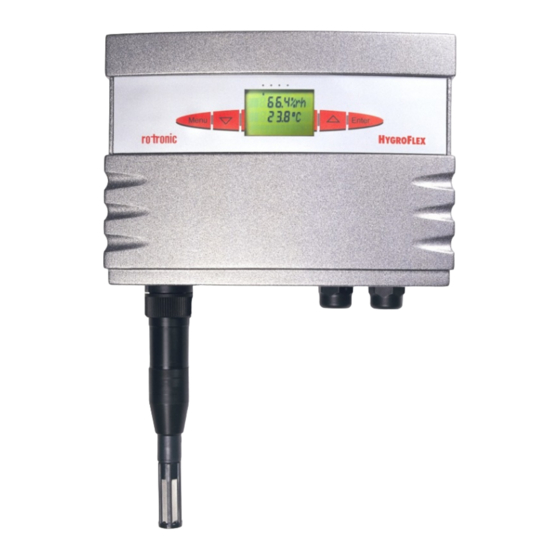
Humidity Temperature Transmitter
© 2006; Rotronic AG
HygroFlex
Instruction Manual
Version 4
Rotronic AG
Bassersdorf, Switzerland
Unit
Instruction Manual
Page
1 of 61
IN-E-HyFlex-V2_10.doc
Document Type
Advertisement
Table of Contents

Related Manuals for Rotronic HygroFlex


Summary of Contents for Rotronic HygroFlex
- Page 1 Rotronic AG IN-E-HyFlex-V4_10 Bassersdorf, Switzerland Document code Unit HygroFlex transmitter version 4: instruction Instruction Manual manual Document Type Page 1 of 61 Document title HygroFlex Humidity Temperature Transmitter Instruction Manual Version 4 © 2006; Rotronic AG IN-E-HyFlex-V2_10.doc...
-
Page 2: Table Of Contents
Ethernet local area network ....................14 RS-485 multi-drop network (HygroFlex 2 and 3) ..............15 Selection of the probe supply voltage (main PCB) ............16 Analog signal configuration (HygroFlex 1 and 3 main PCB) ..........17 Mechanical installation.......................18 Installation of the transmitter enclosure ................18 Front cover removal ......................19... - Page 3 Note: Both instrument configuration and adjustment of the HygroClip probes require a PC with the optional ROTRONIC HW4 software version 1.2.2 or higher. Instructions for using the software are not included in this manual. These instructions are shipped separately on the software CD ROM.
-
Page 4: Overview
Overview The HygroFlex are 3-wire humidity temperature transmitters available with a wide variety of probes for use in many different industrial and scientific applications. The HygroFlex series uses a micro- processor based design to achieve unparalleled accuracy, reliability and versatility. - Page 5 Allows the HygroPalm to read the transmitter or to calibrate a digital probe. IMPORTANT: there is no test connector on the HygroFlex 3 when it is equipped with the optional Ethernet (TCP/IP) port. The optional HW4 software offers a reliable networking solution and the possibility of exporting live data to practically any OPC client applications 0..1V, 0..5V, 0..10V, 0..20 mA, 4..20 mA - corresponding to relative humidity, temperature and...
-
Page 6: General Description
When a probe requires calibration or has to be repaired, it can be replaced with another probe in a few seconds. The ROTRONIC HygroClip digital probes are available in different configurations so as to meet the requirements of each application: ©... - Page 7 Rotronic AG IN-E-HyFlex-V4_10 Bassersdorf, Switzerland Document code Unit HygroFlex transmitter version 4: instruction Instruction Manual manual Document Type Page 7 of 61 Document title HygroClip IW for surface mount (area monitoring) max. 85°C (185°F) – wire mesh filter observe temperature limits of transmitter...
-
Page 8: Analog Outputs (Hygroflex 1 And 3)
2.2.2 Analog probes Depending on the model and options, the HygroFlex transmitters can be used with one or two analog probes. Both the scale and unit of the analog input signals can be defined by software. For example, an analog pressure probe may used to provide the local value of barometric pressure for the computation of parameters such as the wet bulb temperature, mixing ratio or enthalpy. -
Page 9: Optional Display And Keypad
200 units. Any of the 3 analog outputs of the HygroFlex 3 can be set to correspond to humidity [probe 1 or 2] or temperature [probe 1 or 2] or calculated parameter [probe 1 or 2] or user defined calculation or optional analog probe signal (such as pressure). -
Page 10: Serial Interface (Hygroflex 2 And 3)
HygroPalm calibrator. Serial interface (HygroFlex 2 and 3) Both the HygroFlex 2 and 3 have an external receptacle (located on the connector plate) that provides both a RS-232 and a RS-485 interface. A special connector matching this receptacle is shipped with the HygroFlex. -
Page 11: Optional Ethernet (Tcp/Ip) Interface (Hygroflex 2 And 3)
Baud rate. Optional Ethernet (TCP/IP) interface (HygroFlex 2 and 3) As an option, both the HygroFlex 2 and HygroFlex 3 can be ordered with the combination of an Ethernet (TCP/IP) interface and a RS-485 serial interface. The HW4 software accepts connection to the PC by means of an Ethernet network. -
Page 12: Optional Configuration And Communication Software
The HygroFlex is configured by the factory as specified when the instrument was ordered. The configuration can be modified by the user and this requires connecting the HygroFlex to a PC with the ROTRONIC HW4 software installed (version 1.2.2 or higher). -
Page 13: Internal Service Connector (Hygroflex Configuration)
COM port of a PC. Use of the MTA service connector is limited to configuring the instrument (unit system, output range, display, etc.). Both the HygroFlex 2 and HygroFlex 3 can also be configured via one of the external digital ports. -
Page 14: Baud Rate Compatibility Requirements
19200 bps: HygroPalm and HygroLab indicators, HygroFlex and M33 transmitters, HygroClip Alarm programmable alarm card, HygroClip DI interface, HygroStat MB Thermo-Hygrostat The factory default Baud rate of the HygroFlex is compatible both with both the ROTRONIC HW4 and HW3 software and is the recommended Baud rate for the HygroFlex. -
Page 15: Rs-485 Multi-Drop Network (Hygroflex 2 And 3)
Both the HygroFlex 2 and HygroFlex 3 feature a RS-485 connector. When the number of available PC ports is limited, this connector can be used to connect together up to 64 HygroFlex (or other devices) in a multi-dropped arrangement. In principle, an unlimited number of such networks can be monitored with the HW4 software, but each RS-485 multi-drop network is limited to 64 devices. -
Page 16: Selection Of The Probe Supply Voltage (Main Pcb)
- All devices within a multi-drop should use the same Baud rate. See Baud rate compatibility requirements. - Models with Ethernet (TCP/IP) interface: please note that the Baud rate of the HygroFlex and the Baud rate of the internal Ethernet module should be set to the same value. -
Page 17: Analog Signal Configuration (Hygroflex 1 And 3 Main Pcb)
Document title Analog signal configuration (HygroFlex 1 and 3 main PCB) On the HygroFlex 1 and HygroFlex 3, the type of analog output signal can be selected by means of jumpers on the PCB: HygroFlex 1: to configure the temperature range and unit, use this 3-pin service connector and connect to a PC with cable # AC1623. -
Page 18: Mechanical Installation
Document title Mechanical installation Each HygroFlex transmitter is shipped in an individual box, separately from the probe. The shipping box has a label with the following information: instrument type, main specifications and serial number. An identical label is located inside of the transmitter enclosure. -
Page 19: Front Cover Removal
Rotronic AG IN-E-HyFlex-V4_10 Bassersdorf, Switzerland Document code Unit HygroFlex transmitter version 4: instruction Instruction Manual manual Document Type Page 19 of 61 Document title Front cover removal The front cover is held in place by 4 small tabs molded into the electronics housing. To remove the cover, insert a screwdriver in the V-shaped slot on top of cover and press lightly to unlock prior to pulling the cover away from the electronics housing. -
Page 20: Front Cover Installation
Document code Unit HygroFlex transmitter version 4: instruction Instruction Manual manual Document Type Page 20 of 61 Document title Front cover installation To put the front cover back on the HygroFlex, proceed as shown below: © 2006; Rotronic AG IN-E-HyFlex-V2_10.doc... -
Page 21: Re-Attaching The Ribbon Cable (Cover With Optional Display And Keypad)
Rotronic AG IN-E-HyFlex-V4_10 Bassersdorf, Switzerland Document code Unit HygroFlex transmitter version 4: instruction Instruction Manual manual Document Type Page 21 of 61 Document title Re-attaching the ribbon cable (cover with optional display and keypad) Zero-insertion-force connectors are used for the ribbon cable that connects the cover and the main printed circuit board. -
Page 22: Probe Installation Guidelines
Connect the probe to probe input 1 (main probe input). Except for probe model IW (area monitoring); probes are connected to the HygroFlex by means of a cable (attached to the probe). Do not remove the dust filter or slotted cap from the probe. Both sensors can easily be damaged when not protected. -
Page 23: Electrical Installation
(except HygroFlex 2) 1 : Out 1 (+) 2 : Out 2 (+) 3 : Out 3 (+) – HygroFlex 3 only 4 : GND (common) All terminal blocks on the main PCB are of the plug-in type so that the connector plate can be pulled out if required. -
Page 24: Optional Ethernet Module (Hygroflex 2 And 3)
Document Type Page 24 of 61 Document title Optional Ethernet module (HygroFlex 2 and 3) Optional Ethernet Module Mains fuse Starting with PCB number 66.0738.0602, all models are equipped with a SMD fuse (250 VAC / 1 A T) soldered on the main PCB. -
Page 25: Pcb Number
Connector plate Standard connector plate (all models) Note: The drawing below shows the maximum number of connectors and cable grips. The actual number of connector depends on the model number (HygroFlex 1, 2 or 3). © 2006; Rotronic AG IN-E-HyFlex-V2_10.doc... - Page 26 Connector plate for models with the optional Ethernet interface HygroFlex 2: Grommet for Ethernet cable HygroFlex 3: Grommet for Ethernet cable Note: the HygroFlex 3 with the optional Ethernet interface does not have an external test connector. © 2006; Rotronic AG IN-E-HyFlex-V2_10.doc...
-
Page 27: Connector Plate Connectors - Pin-Out Diagrams
Rotronic AG IN-E-HyFlex-V4_10 Bassersdorf, Switzerland Document code Unit HygroFlex transmitter version 4: instruction Instruction Manual manual Document Type Page 27 of 61 Document title Connector plate connectors - pin-out diagrams Note: the contact side of the female connector is the same as the solder side of the matching male connector. -
Page 28: Electrical Diagrams (Analog Outputs)
Rotronic AG IN-E-HyFlex-V4_10 Bassersdorf, Switzerland Document code Unit HygroFlex transmitter version 4: instruction Instruction Manual manual Document Type Page 28 of 61 Document title RS232 connection (DB9 female connecting to a PC or terminal server) Viewed opposite from solder side... - Page 29 Rotronic AG IN-E-HyFlex-V4_10 Bassersdorf, Switzerland Document code Unit HygroFlex transmitter version 4: instruction Instruction Manual manual Document Type Page 29 of 61 Document title 90…264 VAC with optional power module and current output signals 1) maximum load : 500 ohm wiring included.
-
Page 30: Cable Grips
Seal any unused cable grip. On request, the connector plate is available with 1/2” conduit adapters instead of cable grips. We strongly recommend running the analog output signal cable separately from the power cable. Grommet for the Ethernet cable (HygroFlex 2 and 3 option) © 2006; Rotronic AG IN-E-HyFlex-V2_10.doc... -
Page 31: Grounding
(see separate instructions on the software CD ROM). With HW4 a Baud rate of either 19200 or 57600 may be used. As far as possible, use a Baud rate of 19200 for the HygroFlex and make sure that all devices in the multi-drop are set to the same Baud rate. Proceed as follows: 1) By default, all transmitters are shipped by the factory with RS address 0. -
Page 32: Hygroflex Function Menu
RS-485 cable. HygroFlex function menu The functions of the HygroFlex can be accessed either with the optional display and keypad or by connecting a HygroPalm indicator to the Test connector of the HygroFlex (see Remote Mode). -
Page 33: Calculate (Hygroflex 2 And 3)
. Any selection made here has no effect on analog output #3 (computed parameter) of the HygroFlex 3. Use the HW4 software to change the computed parameter sent this output. 1) Does not apply to third-party analog probes. The calculated parameter is selected individually for each probe connected to the instrument Prior to entering this function, select on the display the probe input to program. -
Page 34: Display
Document Type Page 34 of 61 Document title software. Both the HygroFlex 2 and HygroFlex 3 can also be programmed to accept the input from a pressure probe (variable pressure value). DISPLAY Definition This function is used to select which parameters are displayed by the optional display of the HygroFlex 2 and HygroFlex 3. - Page 35 For best accuracy, we recommend using a T-low value close to 20°C (68°F). c) When calibrating relative humidity (2, 3 or 4 points) with the ROTRONIC humidity standards, always follow the sequence 35 %RH, 80 %RH, 10 %RH or 5 %RH, 0 %RH. When using a...
-
Page 36: Adjust 1Pt
ADJUST 1PT Definition The Adjust 1PT function permits to do a 1-point adjustment (offset adjustment) of a ROTRONIC HygroClip digital probe against a known reference environment. This function is limited to a simple offset adjustment that is applied across the entire measuring range. To prevent unauthorized or accidental changes, lock the keypad (software configuration) to block out access to this function either from the keypad or from the HygroPalm calibrator. -
Page 37: Adjust Ref
Note: this function is not available with the HygroFlex 1 (single probe input). When two ROTRONIC HygroClip digital probes are connected to the HygroFlex, the Adjust REF function permits to do a 1-point adjustment (both humidity and temperature) of probe 1, using probe 2 as a reference. -
Page 38: Probe
Signal stability is first evaluated after 60 seconds into the measurement and is updated every 30 seconds. HygroFlex 2 and 3: when the trend indicator is enabled, the symbol for the calculated parameter (e.g. Dp for dew point) is no longer displayed to the left of the numerical value. -
Page 39: Sys Status
When entering the function, analog output 1 is displayed first. Use the UP or the DOWN key to display the other outputs. Error and status messages The following is a list of coded messages (101, etc.) that the HygroFlex may show on the bottom line of the optional LC display or via PC interface. Errors: checksum error The checksum test did not pass during RS-communication. -
Page 40: Test Connector For The Hygropalm Indicator
Calibration adjusted Test connector for the HygroPalm indicator NOTE: The HygroFlex 3 equipped with the optional Ethernet interface does not have a Test connector. Definition The test connector permits to connect a HygroPalm indicator to the HygroFlex (the HygroPalm goes automatically into its Remote Control Mode). -
Page 41: Display The Probe Measurements
HygroPalm act like if they were the display and keyboard of the transmitter. The definition of these functions and the procedure to be followed are the same as already described under HygroFlex Function Menu. 1) applies only to the ROTRONIC HygroClip digital probes ©... -
Page 42: Function Adjust Ref
HygroPalm prior to entering the function menu will be adjusted. b) REF = FLEX (HygroFlex 2 or 3): this is available only when the HygroFlex has 2 probe inputs and the reference is always the probe connected to input 2 of the HygroFlex. Probe 1 will be adjusted (1-point) to match probe 2. -
Page 43: Maintenance
On-site maintenance a) Probe maintenance Each HygroFlex transmitter has a test connector that is located on the connection plate. The HygroPalm 2 and HygroPalm 3 portable indicators can be connected to this connector with cable AC1620. Using the probe of the HygroPalm as a reference, any HygroClip digital probe connected to the transmitter can be read and adjusted at one humidity and temperature value. - Page 44 Periodic calibration check Long term stability of the ROTRONIC Hygromer humidity sensor is typically better than 1 %RH per year. For maximum accuracy, calibration of the probe should be verified every 6 to 12 months. Applications where the probe is exposed to significant pollution may require more frequent verifications.
-
Page 45: Specifications
Rotronic AG IN-E-HyFlex-V4_10 Bassersdorf, Switzerland Document code Unit HygroFlex transmitter version 4: instruction Instruction Manual manual Document Type Page 45 of 61 Document title Specifications Operating Voltage standard 12 to 35 VDC / 300 mA max. or 12 to 24 VAC... - Page 46 Specify engineering units and range when ordering (both can be changed by the user with optional HW4 software). See separate probe specifications regarding the different range limits Not available with the HygroFlex 1. The accuracy of the computed parameter is limited by the accuracy of the measured parameters on which it is based The standard factory setting is frost point for values below freezing.
-
Page 47: Probe Calibration Basics
Calibration using a PC with the optional HW4 software (see separate software instructions). This choice is available only with the HygroFlex 2 and HygroFlex 3. d) Calibration of the probe alone (removed from the transmitter), using a PC with the optional HW3 software and the T7-03-WIN calibration cable (see separate software instructions). -
Page 48: Humidity Calibration
ERV-15 for probe type IW Certified humidity standards The ROTRONIC certified standards are available in boxes of 5 glass ampoules of the same value, which can be stored indefinitely. Standards in the range of 5 to 95 %RH are non- saturated aqueous salt solutions that are precisely titrated at our factory for the right concentration. -
Page 49: Humidity Definitions
Rotronic AG IN-E-HyFlex-V4_10 Bassersdorf, Switzerland Document code Unit HygroFlex transmitter version 4: instruction Instruction Manual manual Document Type Page 49 of 61 Document title • Tap the top of the ampoule so that all liquid drops to the bottom of the ampoule. Snap off top and empty contents on fiber disc. - Page 50 Rotronic AG IN-E-HyFlex-V4_10 Bassersdorf, Switzerland Document code Unit HygroFlex transmitter version 4: instruction Instruction Manual manual Document Type Page 50 of 61 Document title Wet bulb temperature The wet bulb temperature of moist air at pressure Pb, temperature T and mixing ratio r is the...
- Page 51 Rotronic AG IN-E-HyFlex-V4_10 Bassersdorf, Switzerland Document code Unit HygroFlex transmitter version 4: instruction Instruction Manual manual Document Type Page 51 of 61 Document title Q [g / kg] = 1000 p / (1.6078 P – 0.6078 p) 1 gr (grain) = 0.0648 g (gram) 1 lb = 0.4535923 kg...
-
Page 52: Dew Point Accuracy
BTU / lb Dew point accuracy Both the HygroFlex 2 and the HygroFlex 3 use the relative humidity and temperature measurements to compute another parameter such as dew point, mixing ratio, enthalpy, etc. The accuracy of this conversion varies, depending on the humidity and temperature conditions. Typical... -
Page 53: Ascii Communications Protocol
Data bits Stop bits Use these settings to configure a third-party software used to communicate with the HygroFlex (see ASCII commands provided in this manual). Also use these settings to configure a device server (connection of a serial device to an Ethernet LAN). Set flow control to none and, if necessary, force incoming data to 7-bit ASCII. - Page 54 Rotronic AG IN-E-HyFlex-V4_10 Bassersdorf, Switzerland Document code Unit HygroFlex transmitter version 4: instruction Instruction Manual manual Document Type Page 54 of 61 Document title ASCII communications protocol Communication with the instrument is always initiated from the PC. Any ASCII string sent from the PC should begin with the { character to start the synchronization.
- Page 55 0015.82: temperature probe 1 (°C as per instrument configuration) -003.69: dew point probe 1 (°C as per instrument configuration), etc. 3) Read %RH and temperature from the HygroFlex 3 (1 probe) with address 00, connected by RS485 to the HygroFlex 2: Data request |{M00RDD} +CR note: the | character (ASCII 124) preceding the command Answer: {M00RDD 0020.41;0019.87;----.--;----.--;#E...
-
Page 56: Metal Enclosure Option
0019.87: temperature probe 1 (°C as per instrument configuration), etc Metal enclosure option As an option, the HygroFlex is available in an aluminum enclosure with a hinged cover - with or without display and keypad. The electrical connections are arranged like on the standard models. -
Page 57: Accessories For The Hygroflex
ROTRONIC products that have a RS-485 serial port. The HCA makes it possible to implement alarm functions that would not be available with either the HygroFlex alone or with the combination of the HygroFlex and a PC with the HW4 software. For example, the HCA makes it © 2006; Rotronic AG... -
Page 58: Electrical Installation Guidelines
The HCA operates as a stand alone device or can be integrated in a network monitored by a PC with the HW4 software. For more details, contact your local ROTRONIC representative or visit our website: www.rotronic-usa.com... - Page 59 Rotronic AG IN-E-HyFlex-V4_10 Bassersdorf, Switzerland Document code Unit HygroFlex transmitter version 4: instruction Instruction Manual manual Document Type Page 59 of 61 Document title • direct and alternate current > 400 V (unshielded) in separated bundles or channels / •...
-
Page 60: Document Releases
15 VDC power supply. A third party analog probe may also require a supply voltage of more than 5 VDC (HygroFlex 2 and HygroFlex 3). Move jumper B20 to B19 to supply all probes with 15 VDC. There is no connection between signal ground and terminal 3 of the power terminal block (TB1). If so desired, a connection can be established by closing solder pad B18, next to TB1. - Page 61 HygroFlex models can be configured with the ROTONIC HW4 software (version 1.2.2 or higher). HW4 can read / record data from both the HygroFlex 2 and HygroFlex 3, and can be configured to monitor alarms triggered by these devices. The HygroFlex transmitter is still backward compatible with the ROTRONIC HW3 software ©...
Need help?
Do you have a question about the HygroFlex and is the answer not in the manual?
Questions and answers