Advertisement
Quick Links
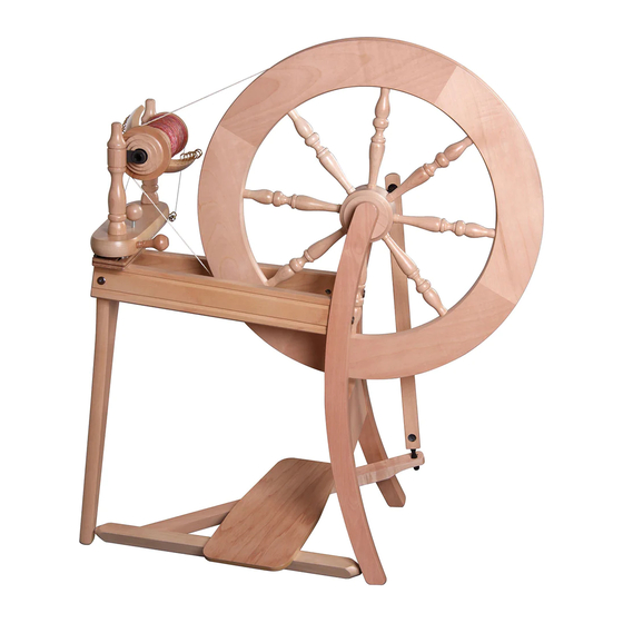
TRADITIONAL SPINNING WHEEL
ASHFORD TRADITIONAL SPINNING WHEEL
SINGLE DRIVE
SINGLE DRIVE
Ashford Handicrafts Limited
Factory and Showroom: 415 West Street
PO Box 474, Ashburton 7700 New Zealand
Telephone 64 3 308 9087
Email: sales@ashford.co.nz Internet: www.ashford.co.nz
INSTRUCTIONS
ASHFORD TRADITIONAL SPINNING WHEEL
DOUBLE DRIVE
TDSW140519V13
Ashford Guarantee
Thank you for purchasing this Ashford product. In the unlikely event there is
any fault in manufacture, please contact the dealer you purchased it from. To
validate the guarantee, please go to www.ashford.co.nz/product-registration
or email us.
DOUBLE DRIVE
TDSW-DDSW030920V1
DDSW140519V1
Advertisement

Related Manuals for Ashford TRADITIONAL SPINNING WHEEL


Summary of Contents for Ashford TRADITIONAL SPINNING WHEEL
- Page 1 Ashford Guarantee Factory and Showroom: 415 West Street Thank you for purchasing this Ashford product. In the unlikely event there is PO Box 474, Ashburton 7700 New Zealand any fault in manufacture, please contact the dealer you purchased it from. To Telephone 64 3 308 9087 validate the guarantee, please go to www.ashford.co.nz/product-registration...
- Page 3 Real Scale Hardware List...
- Page 5 Set the treadle assembly on the edge of a table. Insert the conrod joint into the large slot in the treadle rail. Note the crank bearing faces the back of the spinning wheel. Hold the conrod With both hands, joint with one hand turn the conrod on either side of the joint a ¼...
- Page 6 Wax the steel rods in the treadle rail. Loosely attach the wheel support to the side rails with bolts and barrel nuts. Then locate the treadle rail into the holes in the legs.
- Page 7 Insert the crank shaft into the wheel support. Tighten every bolt extra firmly with the allen key. Then remove the crank.
- Page 8 Align the wheel and hole in Align the wheel and hole in the crank shaft with the the crank shaft with the groove in the hub using a groove in the hub using a lazy kate wire. lazy kate wire. Carefully tap the hub Carefully tap the hub pin through the hub...
- Page 9 SINGLE DRIVE Thread 12 hooks into Step 12 - 21 For Single Drive only. For Double Drive go to Step 22. the flyer. Thread 12 hooks into the flyer. Screw 12 hooks into the flyer Assemble the flyer unit. Assemble the flyer unit. Check the shape of the Check the shape of the nylon bearing on each...
- Page 10 Place the bobbin, small end first, onto the flyer. Then locate the flyer into the bearings. Thread the screw eye into the side of the maiden bar, and screw hook into the opposite side.
- Page 11 Tie the threading hook to the front maid upright with tape. Attach the flyer unit to the side rails with 2 screws and washers, do not tighten yet. Move the flyer unit until the wheel and large flyer pulley are aligned. Then tighten the screws.
- Page 12 Check the end of the adjusting knob is not protruding beneath the maiden bar. Then place the drive belt around the wheel and large flyer pulley. Tie the drive belt and cut off the extra. Single drive ratios: The ratio with the drive belt around the large flyer pulley is approx.
- Page 13 Thread 12 hooks into the DOUBLE DRIVE flyer. Step 22 - 32 For Double Drive only. For Single Drive go to Step 12. Thread 12 hooks into the Thread 12 hooks into the flyer. flyer. Thread 12 hooks into the flyer.
- Page 14 Place the bobbin, small end first, onto the flyer followed by the flyer whorl. Then locate the flyer into the bearings. Thread the screw eye into the side of the maiden bar, and screw hook into the opposite side.
- Page 15 This wheel can be used either double drive or single drive. When spinning double drive the brake band is stored around the back of the maid upright with the drive band around both the large flyer and small bobbin pulley. When spinning single drive the drive band is around the large flyer pulley and the brake band...
- Page 16 Check the end of the adjusting knob is not protruding beneath the maiden bar. Then place the drive belt around the wheel and large flyer pulley then around the wheel again and small bobbin whorl. Tie the drive belt and cut off the extra.
- Page 18 How to insert the polyurethane conrod joints into the conrod. *This has been pre-assembled in the factory. Ashford Handicrafts Limited Factory and Showroom: 415 West Street PO Box 474, Ashburton 7700 New Zealand Telephone 64 3 308 9087 Email: sales@ashford.co.nz Internet: www.ashford.co.nz...
Need help?
Do you have a question about the TRADITIONAL SPINNING WHEEL and is the answer not in the manual?
Questions and answers