Advertisement
Quick Links
Thank you for purchasing your Xtend Garden Building from Forest Garden. Simply follow these step by step
instructions and our top tips for a straightforward assembly. If you have any questions or need advice, our
friendly team is here to help.
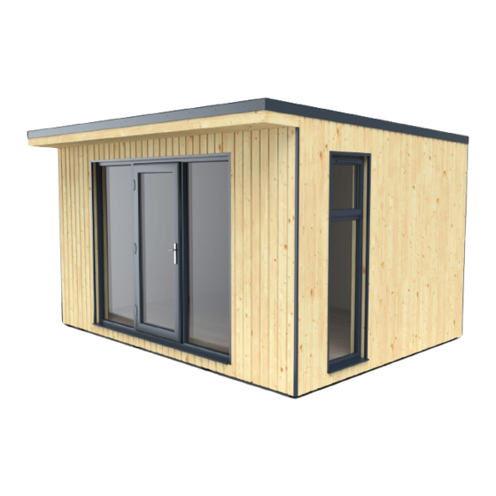
XTEND 4.0 GUIDE BOOK
(4.0x3.0M)
Missing something?
Call our aftersales team on
0333 777 7089
Forest Garden, Oak Drive, Hartlebury Trading Estate, Hartlebury, Worcestershire, DY10 4JB
Need more information?
Call our technical team on
0333 321 3142
ISSUE: 0221
FIXING PACK CODE: XTENDFP
Visit our website for more
information
www.forestgarden.co.uk
Advertisement

Subscribe to Our Youtube Channel
Related Manuals for Forest XTEND 4.0


Summary of Contents for Forest XTEND 4.0
- Page 1 ISSUE: 0221 FIXING PACK CODE: XTENDFP Thank you for purchasing your Xtend Garden Building from Forest Garden. Simply follow these step by step instructions and our top tips for a straightforward assembly. If you have any questions or need advice, our friendly team is here to help.
-
Page 2: Tools Required
‘Fixtures & Fittings’ Box Contents All of our Xtend garden buildings are constructed in the same way. They simply come with slightly different components depending on the size you have purchased. Don’t worry if your ‘fixtures and fittings’ box contains many extra fixings at the end of the build (you haven’t missed a bit!). We have sent you a generic fixtures and fittings box to suit the Xtend garden building collection. -
Page 3: Health And Safety
Health and Safety We strongly recommend that PPE (Personal Protective Equipment) is used throughout your Xtend garden building assembly to ensure you are protected from any potential health and safety risks. Do not exempt yourself from wearing PPE even if the job ‘only takes a few minutes.’ Use any guidance stated on the supplied fixings and where you feel it is applicable to use PPE as part of your step by step assembly. -
Page 4: Before You Start
In general, it does not require any special skills, but it will require a logical approach and will sometimes require some general carpentry. If you have any doubts as to your ability, you should contact Forest Garden and arrange for a professional team to assemble the building for you. - Page 5 Lay the bearers down and spread them out roughly Place the first floor panel (D) on flush to the edge ready to position the floor panels on top. of the first bearer and halfway onto the second bearer. Place the black underside of the floor panel on top of the bearers as shown above.
- Page 6 Using a rubber mallet, knock the second panel into Knock on the front and back of the second panel the first for a tight fit. to ensure it is flush on both edges to the first panel and floor bearers. Using 4 x 35mm screws, pre-drill and screw where Place the fourth floor panel (F), knock into the the adjoining panels intersect.
- Page 7 The components provided will be labelled Insert and knock the floor capping (AN) into place according to the components list at the back of using a rubber mallet. Ensure it is flush to all this guide book. edges. Pre-drill and use 4 x 125mm screws ensuring Position OSB floor sheets (AE) on top of the floor each screw goes into the bearer beneath.
- Page 8 Start to unwrap the DPC roll and choose a starting Continue to wrap around the base. We suggest point on the base’s outer face. Ensure it covers half one person unwraps while the other follows of the bearers and staple into place. behind stapling the DPC into place.
- Page 9 As part of your assembly pack, you will have been Starting with the back Floor Plate (AP), ensure it provided with an OSB offcut to use as an 11mm is flush at each end and use the 11mm offcut to guide when positioning the floor plates.
- Page 10 WALL PANEL LAYOUT SPLINE (Q) INBETWEEN YOUR WALL PANELS SIDE SIDE PANEL 4 (J) SIDE PANEL 2 (K) SIDE PANEL 2 (K) PANEL 3 (L) SIDE PANEL 4 SIDE PANEL 4 SIDE PANEL 2 SIDE PANEL 2 WINDOW PANEL SIDE PANEL 4 WINDOW INSERT (AA) WINDOW PANEL...
- Page 11 Working in the back left corner, add the expanding Pre-drill and, using the star drill bit provided in foam into the side groove of the Side Panel 4 (M) your fixing box, screw through the back into the and butt it up against Side Panel 4 (J). Have one side wall panel using 3 x 150mm screws (top, person holding onto the wall panel to prevent middle and bottom).
- Page 12 Install the Window Panel (N1) as shown above, Install the Front Panel (P) and butt up against the leaving the provided space for the window insert. front side wall panel installed in the previous step. This is labelled on the layout. Ensure all edges are flush.
- Page 13 Insert the Lintel (T) and knock into place. Ensure it Use 35mm screws to secure the lintel in place by is flush to the top of the front panels. screwing from both outside and inside of each wall panel into the lintel. This will use a total of 8 x 35mm screws.
- Page 14 Insert the Front Wall Plate (AP), knocking into Pre-drill and secure with 4 x 125mm screws. place. Expect this to be tight fitting. Ensure it is Repeat the same process for the Back Wall Plate flush to the top and ends. (AP).
- Page 15 Lift up the first Roof Panel (X). Ensure at least 3 Use the spirit level to ensure the top OSB sheet of adults help carefully lift up the roof panels as they the roof panel is flush with the back edge of the are heavy.
- Page 16 Knock further into place to allow the roof panel to Pre-drill and secure 5 x 35mm screws where the be as flush as possible to the wall face. adjoining panels intersect. Repeat the same process as the first roof panel If there is a 2-5mm overhang on the side, don’t using 4 x 150mm screws along the edge to fully worry.
- Page 17 Begin to unwrap the breathable membrane. Starting with the bottom section, pull the Position the membrane 45mm from the ground. membrane tightly and staple into place. Then wrap the excess around the corner and Continue unwrapping the membrane, pulling staple the starting point into place. tightly and stapling into place.
- Page 18 Using a Stanley knife, remove the excess from the Repeat the same process to remove the excess door section, using the walls as a guide to ensure from the window section. it is cut straight. Using the excess membrane, cover the front flush Staple into place and remove the excess from the up to the roof.
- Page 19 T&G CLADDING LAYOUT T&G SIDE PANEL 6 T&G SIDE PANEL 2 T&G SIDE PANEL 1 (AX) (BI) (AZ) T&G SIDE PANEL 4 (BB) T&G SIDE PANEL 4 (BB) T&G SIDE PANEL 5 T&G SIDE PANEL 5 (BH) (BH) T&G WINDOW T&G SIDE PANEL 3 PANEL (BA)
- Page 20 Continue onto the side panels (BB). Knock the first Use 6 x 80mm screws per panel. Ensure you use panel in place and ensure it is butted up against 3 x 80mm screws down each side of the cladded the back panel overhang. panel.
- Page 21 Install the Front T&G Panel (BE). Ensure it is butted Use 3 x 80mm screws to secure the Window up against the side panel and flush to the door Opening Panel (BC) to the Front T&G Panel (BE). section. Secure the panel with 6 x 80mm screws (3 screws down each side).
- Page 22 Unwrap the EPDM out onto the floor first. Then Fold the EPDM back to half way across the roof measure out on the roof to ensure an equal - we recommend two people for this. Be careful overhang around all edges. when moving on and around the roof to prevent any possible injuries.
- Page 23 Secure the Back Roof Battens to the Back T&G To install the Angled Roof Battens, lift the EDPM Panels (AX, BI & AZ). You will need to lift up and slot the matching batten’s listed in the the overhanging EPDM to do this. Ensure each components list into place above each T&G Side batten’s edge is flush to the top of the T&G panel.
- Page 24 Install the piece cut to size in Step 134. Ensure it Use the clips provided to secure where the pieces is flush to the front edge and butts up against the join. Repeat the same process on the opposite plastic trim already pinned into place. side.
-
Page 25: Window Frames
Remove any packaging from the new frame and Remove the timber excess from the window section before inserting the window frame. Take screw the sill into the bottom of the frame. Use 2 x 50mm screws and ensure not to penetrate the out any screws in this section and cut with a saw, using the inner edge as a guide. - Page 26 Attach the window handle with the screws Using a chisel, break off the excess ends of the provided. Remove the hole caps and drill the packers to create a neat finish. Remove the screws into the space provided. Then replace the beading around the edge, ready for the glazing to hole caps.
- Page 27 Place the ledge onto the silicone. Ensure it is Lift and angle the frame, then insert the ledge. level and the back edge meets the first edge of Butt up against the wall panel. the back OSB sheet (the same positioning as the window).
- Page 28 Remove the plastic strips from the bottom of the Drill 150mm from the both internal sides of the door frame. Keep hold of these pieces to reapply double doors. Use 112mm screws to screw into afterwards. place at each side into the bottom of the frame as shown above.
- Page 29 Apply silicone and stick the packers at diagonal As the pane is positioned, the beading can be opposing corners. Place the pane into position, installed using a small rubber mallet and tapped ensuring it is centralised and packed correctly, securely back into place. holding the pane square.
- Page 30 Remove all excess expanding foam around the If any of the 50 x 12mm door and window boards window and door frames. Preferably, wait for the are slightly oversized, you will need to measure out expanding foam to cure for easier removal. your required length.
- Page 31 Position the top plastic ‘L’ strip across the door. Using the pins provided with the trims, hammer 2 Pre-drill the face underneath and fix first. in each corner and 1 in the middle. Pre-drill across the top and repeat the same The side plastic trims for the door and window will process.
- Page 32 Begin at the back and position the first 45 x 28mm Repeat the process at the bottom of the wall, batten flush to the top. This will be the correct ensuring the second batten is flush with the floor length to fit in the space end to end. Use 5 x and end to end.
- Page 33 Using 4 x 80mm screws, secure a batten between Secure four 45 x 28mm battens onto the left hand the two added in Step 206. Repeat on the other wall in line with and at the same height as the four side of the door.
- Page 34 Move onto the front beaded boards. There will be On the side panels, work from the front to the two ‘L’ shaped pieces on either side of the door. back. Ensure the window board is flush to the Use 10 x 50mm screws to secure. Use 6 x 50mm window edges.
- Page 35 Start from the left side. Ensure the rounded edge Use 4 x 50mm screws on each side and 2 x 50mm is butted up against the side and back panels. You screws in the centre of the panel. will need at least one person to hold the panel up whilst the other screws it into place.
- Page 36 Install the internal sides on either side of the door. Install the 45mm overlapping framing on top of Trim to fit if necessary. Use 5 x 60mm nails for each the beaded panel. Ensure this is flush to the inner board to secure.
- Page 37 Secure the small trims at the front and back first. Secure the roof trims on each side, between the Ensure the trims are flush end to end and they are front and back. Ensure these are flush end to end in contact with the roof as much as possible.
- Page 38 Xtend Garden Building Aftercare After your Xtend garden building has been built, steps are required to ensure the building is rot-proof, weatherproof and watertight. Carrying out these steps will ensure your Xtend garden building is protected and durable. Detailed below are the steps required and the best way to accomplish them. Protecting against rot.
- Page 39 The two most common types of high quality exterior wood finish are penetrating finish and film finish. Penetrating finishes are predominantly oil or wax based and they work by soaking into the surface layers of timber to provide a tough, durable, weather resistant finish. These finishes are extremely thin in viscosity in order to penetrate the microscopic pores of timber.
- Page 40 3. Adding Interior Finishes (and Electrics) Once you have completed the exterior treatment, you can begin to adapt the interior to suit you and your working environment. Once constructed, the Xtend interior is as follows: walls and roof with a beaded profile and attractive olive-green finish;...
- Page 41 Xtend Garden Building Components List Use this checklist to ensure you have all the required parts for the build. Refer to the part code, if you need to order a replacement. The components provided will be heavy. Please lift with caution and with a minimum of 2 people. 4.0x3.0M Xtend Garden Building (Xtend4.0) Part Code Description...
Need help?
Do you have a question about the XTEND 4.0 and is the answer not in the manual?
Questions and answers