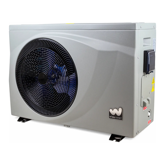
W'eau WFI-007 Installation & Operation Manual
Swimming pool heat pump
Hide thumbs
Also See for WFI-007:
- Installation & operation manual (64 pages) ,
- Installation & operation manual (76 pages)

Subscribe to Our Youtube Channel
Related Manuals for W'eau WFI-007


Summary of Contents for W'eau WFI-007
- Page 1 Installation & Operation Manual Swimming Pool Heat Pump Model No.: WFI-007/010/013/017/021 Thank you very much for purchasing our product,please keep and read this manual carefully before you install heat pump.
- Page 3 Fluorinated greenhouse gas – (R32) The device contains the fluorinated greenhouse gas (R32) which is required for the device to work. Industrial designation HFC-32 Common designation Global warming potential (GWP) Further information can be found on the device itself or the Specifications. WARNING! Risk of fire and explosion through leaking finned heat exchanger! The refrigerant circuit of the finned heat exchanger contains highly pressurised, easily flammable,...
-
Page 4: Table Of Contents
excluded in the event of repairs carried out on your own, improper operation. - Ensure that children do not insert any objects into the fan blade and heat pump. - Ensure that the electrical system to which the heat pump is connected has an earth conductor. - If the unit would be installed where is vulnerable to lightning stroke, lightning protection measurements must be carried out. -
Page 5: Accessories Description
1. Accessories description Each unit produced by our factory is with the following accessories: Name Qty. Instruction Manual 1 PC Guide users to install the system Drain-pipe 1 PC Used for draining the condensate water Drain-pipe connector 1 PC Connect the drain pipe to the heat pump unit Rubber shock absorber 4 PCS Reduce vibration and reduce noise... -
Page 6: Attention For Safety
2. Attention for safety Range of application: 1.Power supply: 220~240V/1N~50/60Hz. 2.Environment temperature: -15°C〜43°C 3.Water temperature range: 8°C~40°C in Heating function 8°C~28°C in Cooling function Confirm the ground connection, if the ground connection is not correctly done, it may cause ● electric shock. -
Page 7: Installation Of The Unit
3. Installation of the unit 3.1 Installation Illustration Above illustration is just for the reference, please take the advice of authorized installers. 3.2 Advised installation space Keep the following indicated space for operation and maintenance when make the installation. - 5 -... - Page 8 3.3 Additional By-pass kits The additional By-pass kits is suggested to be put into the piping system to get the better adjustment of water flow. 3.4 Heat pump unit size WFI-007/010 WFI-013/017/021 - 6 -...
- Page 9 3.5 Heat pump Exploded View Parts Parts Fan protective gill Water flow switch Front panel Titanium heat exchanger Fan blade Right structure Fan motor Manometer Left panel Right panel Left structure Control panel Evaporator Electrical terminal cover Fan motor mount Electrical terminal block Upper structure Electrical cable support...
- Page 10 3.6 Electrical connection Suggested power cable specification Model Power Cable Specification WFI-007/010 3*1.5 mm² WFI-013/017 3*2.5 mm² WFI-021 3*4 mm² Terminal Terminal cable max. 4 mm² Electrical connection Position L,N and is for the power connection of our heat pump.
-
Page 11: Specifications
4. Specifications 4.1 Specifications Model No. WFI-007 WFI-010 WFI-013 WFI-017 WFI-021 * Heating Capacity at Air 26℃, Humidity 80%, Water 26℃ Heating Capacity (kW) 7.6~1.7 10.5~2.3 13.5~3.0 17~3.8 21.1~4.8 Power Input (kW) 1.12~0.11 1.54~0.15 1.99~0.19 2.50~0.24 3.10~0.30 15.8~6.8 15.8~6.8 16~6.8 15.8~6.8... -
Page 12: Electrical Wiring
5. Electrical wiring 5.1 Electric wiring diagram WFI-007/010 - 10 -... - Page 13 WFI-013/017/021 - 11 -...
-
Page 14: Instruction Of Operation
6.Instruction of operation 6.1 Wire controller (Function of buttons) 6.2 Definition of display - 12 -... - Page 15 6.3 Start up & Locking Press the button to switch the heat pump on or off. This button is also used to return to the main interface. When the heat pump is in operation, hold the button for 3 seconds to lock or unlock the controller.
- Page 16 Hold the button for 3 seconds to change the below four operating modes each time: :Mode ECO Inverter: Choose this heating mode that the heat pump operates silently. :Mode Boost Inverter: Choose this heating mode that the heat pump operates powerfully.
- Page 17 6.6 Clock setting Press the button to enter the clock setting interface. Clock display on right bottom flashes. Change the hours using , then press again to go to minute setting, change the minutes using the Press again to confirm the setting and return to the main menu. 6.7 Timer setting Hold the button for 3 seconds to enter the setting of Timer ON &...
- Page 18 Fan Speed : Signal of Water pump : Wi-Fi function Attention: With the indication of the functions or key parts, it is helpful for service team to maintain or repair the heat pump. 6.9 Manual defrosting Hold for 3 seconds to start Manual defrosting function. 6.10 Factory setting recovery Hold for 5 seconds to recover factory setting.
- Page 19 Reserved °C Titanium heat exchanger temperature °C °C Water inlet temperature °C Water outlet temperature Reserved Reserved Reserved Temperature sensor failure Refrigerant system failure Inverter driver failure Device output Running status AC voltage DC voltage Actual frequency EEV open degree Reserved Heat pump current Compressor current...
-
Page 20: Adjusting And Initial Operation
7.Adjusting and Initial operation 7.1 Attention ● Open the valve of water system, inject water into the system, and exhaust air inside. ● Do adjustment after electrical safety inspection. ● After the power is switched on, start the test running of heat pump, to check if it can function well. ●... -
Page 21: Operation And Maintenance
8. Operation and maintenance 8.1 To ensure the well functioning, the system should be checked and maintained after a period of time. During the maintenance, please pay attention to some points below: ● When you need open the cabinet and make inside inspection, please do cut off the electricity power in advance. - Page 22 ● Remove the compressor power cables. ● Remove the compressor fixing screws. ● Remove the compressor. 8.6 Conduct regular maintenance according to the user manual instruction, to make sure the unit running in good condition. ● Fire prevention: if there is a fire, please turn off the power switch immediately, put the fire out with fire extinguisher.
-
Page 23: Error Codes & Solutions
9. Error codes & Solutions Code Description Potential reasons Solutions Check the water circuit system, the opening Insufficient water flow of by-pass kits, the running of water pump E03 Water flow protection Check the wiring and reconnect water flow Water flow switch disconnected switch Water flow switch defective Change a new one... - Page 24 connector) failure Outer piping temp. sensor Sensor disconnected or defective Reconnect or replace sensor (White connector) failure Exhause piping temp. sensor Sensor disconnected or defective Reconnect or replace sensor (Purple connector) failure Ambient temp. sensor (Black Sensor disconnected or defective Reconnect or replace sensor connector) failure Check the water circuit system/ water flow...
-
Page 25: Wifi-Function
10. Wifi-Function 1. Download the ‘Tuya Smart’ App Scan the QR code below to download the mobile APP. Or search ‘Tuya Smart’ in App Store (IOS) or Google play (Android) 2. Sign up for the first time - 23 -... - Page 26 3. Press ‘+’ to add a device 4. Choose ‘Others’ and ‘Other Wifi’ on the interface 5. Put your mobile phone close to the pool heat pump, which are under the same Wifi area - 24 -...
- Page 27 6. Make sure the device is reset, then enter the WIFI account and password to connect Wifi. Reset the Wifi function: Hold the for 3 seconds. - 25 -...
- Page 28 7. Press ‘Confirm’ to start the connection after completing. The device is successfully added if it’s connect, then press ‘Finish’. - 26 -...
- Page 29 8. App Main Interface 9. Functions Remark: The heat pump APP function includes: Turn On/Off the machine Temperature setting and display Mode Selection Failure status display - 27 -...
Need help?
Do you have a question about the WFI-007 and is the answer not in the manual?
Questions and answers