Table of Contents
Advertisement
Quick Links
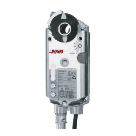
Description
This 24 Vac, non-spring return electronic actuator is designed for modulating
and three-position control of building HVAC valves and dampers.
Features
• Brushless motor technology with stall protection
• Unique self-centering shaft coupling
• Manual override
• 132 lb-in (15 Nm) torque
• 5° preload as shipped from factory
• Mechanical range adjustment capabilities
• Offset and span adjustment models available
• Models with independently adjustable, dual auxiliary switches available
• Built-in 1/2-inch conduit connection
• UL and C-UL listed, CE certified
Product Numbers
Table 1.
DC24-132-T
DC24-132-TA
DCM24-132
DCM24-132-ZA
DC-132 Non Spring Return Electronic Actuator Series
Operating
Product
Voltage
Number
Built-in Control
Control
Options
Delta Control Products, Inc.
2031 West Rose Garden Lane
Phoenix, AZ 85027
623-780-2408
Advertisement
Table of Contents

Related Manuals for Delta DC-132 Series


Summary of Contents for Delta DC-132 Series
- Page 1 Delta Control Products, Inc. 2031 West Rose Garden Lane Phoenix, AZ 85027 623-780-2408 DC-132 Non Spring Return Electronic Actuator Series Description This 24 Vac, non-spring return electronic actuator is designed for modulating and three-position control of building HVAC valves and dampers.
- Page 2 Specifications Power Supply Operating voltage 24 VAC ±20% 24 VAC Frequency 50/60 Hz Power consumption Running: DCM24-132, DCM24-132-ZA 5 VA/4W DC24-132-T, DC24-132-T 3 VA/3W Holding: DCM24-132, DCM24-132-ZA 1 VA/1W Equipment rating Class 2, in accordance with UL/CSA Class III per EN 60730 Input signal (wires 8-2) DCM24-132, DCM24-132-ZA Control Signal Voltage-input...
- Page 3 Actuator Components Legend Actuator housing Positioning scale for angle of rotation DIP switches and cover Span adjustment Offset (start point) adjustment Mounting bracket Connection cable for power and control signals Connection cable for auxiliary switches or feedback potentiometer Manual override 10.
- Page 4 Damper Mounting and Installation • Place the actuator on the damper shaft so that the front of the actuator is accessible. (The label and the manual override button are on the front side.) • The minimum damper drive shaft is 3/4-inches (20mm). The shaft length determines whether the shaft adapter will be mounted on the front or back of the actuator.
- Page 5 The offset (start point) and span of the control signal can be adjusted. The offset, Uo, can Control Signal Adjustment be adjusted between 0 to 5 Vdc. The span, ∆U, can be adjusted between 2 to 30 Vdc. DCM24-132-ZA ∆U (max. 30 V) Factory setting: 30V span Mechanical positioning range (100% = angle of rotation 90°)
- Page 6 DIP Switch Functionality DCM24-132 Description Label Description Function DCM24-132-ZA Counterclockwise Clockwise Rotary Angle Direction Active Self-adaptation to mechanical range 2-10 Vdc 2-10 0-10 0…10 Vdc DCM24-132: Positioning control signal 2-10 or 0-10 Offset 0-5V DCM24-132-ZA: Positioning signal. Span 2-30V Turn on or off capability to adjust offset/span. 0-10 0...10 Vdc Figure 9.
- Page 7 Dimensions min. 4 1-3/16 1-3/16 (100) (30) (30) 47.5˚ 47.5˚ 1-11/16 (42) 8-3/8 (212) 5-9/16 min. 6 (141) (150) 3.25 min. 4 (83) (100) min. 4 3 ft min.2-3/8 (100) (900) (60) min. 1/2 (12) (12) (19) 2-3/8 (60) 1/2" NSPT Figure 12.
Need help?
Do you have a question about the DC-132 Series and is the answer not in the manual?
Questions and answers