Advertisement
Table of Contents
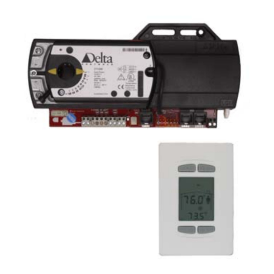
Product Description
The Delta VAV Termination (DZNT) solution consists of an
intelligent LCD thermostat (DZNT-T0-VAV) and remote
termination board (DZTM) for mounting on the VAV/VVT unit.
The thermostat has an LCD display, four pushbuttons for setpoint
and occupancy override, and contains a variety of configurable
VAV/VVT algorithms suitable for controlling all three remote
termination board types.
Every remote termination board comes complete with a damper
actuator, flow sensor for VAV models, and housing. They are also
capable of fan control, reheat control and automatic heat/cool
changeover.
Important Information
1. The Termination Board mounted to the VAV/VVT box is not a programmable
controller. All control and network functions are performed by the DZNT-T0-
VAV.
2. DZNT-T0-VAVs may be part of an MS/TP network or stand-alone. However, a
stand-alone DZNT-T0-VAV does not have a time clock or scheduling functions.
Occupied and Unoccupied periods are determined by airflow or a BAS contact
closure on IP3.
3. DZNT-T0-VAV used for VAV / VVT termination may not be used on LINKnet
networks.
4. Data exchange may be done in GCL programming in any DCU or Application
Controller on the MS/TP network.
5. Because of the fixed objects in the controller, alarming and trending must be
carried out by different controller on the network. Be aware that large numbers of
DER objects will affect the Scan Rate of those controllers. If the requirements call
for trending or alarming, it is recommended that you limit the number of DZNT
VAV devices so a maximum of 200 DER objects are created on any one system
panel.
Cautions or Warnings: This graphic identifies a situation where damage to a
device will occur if the instructions are not followed carefully. To protect the
equipment that you are using, please read and follow the instructions in these notes.
Package Contents
Product: VAV: DZNT-V104D | DZNT-V104T | DZNT-V112A
VVT: DZNT-104D | DZNT-104T | DZNT-112A
DZNT VAV/VVT Installation Guide
Document Edition 1.2
I
NSTALLATION
VAV: DZNT-V104D | DZNT-V104T | DZNT-V112A
VVT: DZNT-104D | DZNT-104T | DZNT-112A
G
UIDE
VAV / VVT Termination:
Document Edition 1.2
Page 1 of 16
Advertisement
Table of Contents

Related Manuals for Delta DZNT-104T


Summary of Contents for Delta DZNT-104T
- Page 1 VVT: DZNT-104D | DZNT-104T | DZNT-112A Document Edition 1.2 Product Description The Delta VAV Termination (DZNT) solution consists of an intelligent LCD thermostat (DZNT-T0-VAV) and remote termination board (DZTM) for mounting on the VAV/VVT unit. The thermostat has an LCD display, four pushbuttons for setpoint...
- Page 2 DZNT VAV / VVT Installation Guide Related Documents DZNT VAV Application Guide: (configuration & programming) Delta Controls Wiring Guidelines Related Documents – Cont. ORCAview Operator Guide ORCAview Technical Reference Manual Release Notes for related Firmware and DZNT-T0-VAV products Actuator Instructions Warning: Do not open the actuator or the controller.
-
Page 3: Warnings And Cautions
Delta Controls Mounting the VAV Termination Board The actuator on one end of the housing fits over the damper shaft on the VAV box. The other end of the plastic housing is secured to the VAV box with a sheet metal screw (through the mounting slots and brass bushing provided). -
Page 4: Mounting Dimensions
DZNT VAV / VVT Installation Guide Mounting Dimensions 1.83 Inch 7.54 Inch 46.3 mm 191.5 mm 5.50 Inch 139.5 mm 4.23 Inch 107.5 mm 2.32 Inch 1.93 Inch 58.9 mm 49.0 mm Damper Shaft 2.02 Inch 2.39 Inch 51.3 mm 60.6 mm 6.99 Inch 177.5 mm... -
Page 5: Mounting The Thermostat
Delta Controls Mounting the Thermostat The DZNT-T0-VAV backplate is designed for mounting directly on a standard North American, European or Australian electrical box, but may be mounted in other ways as well. Wiring Diagram – Thermostat / Termination Board Connections For further wiring details regarding reheat and other applications see the DZNT VAV/VVT Application Guide. -
Page 6: Getting Started
( ) and Down ( ) buttons to adjust the values. a) If the thermostats are connected to a Delta System or Area controller, then set DNA On, and then Set the address to from 1-99. The address must be unique within the MS/TP network segment. The thermostat will automatically inherit the System (Sys), Area (ArE) and OEM* addresses. - Page 7 Delta Controls b) If the thermostat is not connected to a Delta controller, set DNA to Off, and then set the Address (Add), System (Sys) address, Area (ArE) address and OEM* address to a unique number within the network. 4. Exit the Adr submenu : By default OEM address is not used.
- Page 8 DZNT VAV / VVT Installation Guide 2. Command the VAV box to control to the Maximum cooling airflow setpoint to verify that the damper is being controlled properly. The next step, Calibrating the airflow reading, must be done with the assistance of the Air Balancing technician, and can be skipped for now.
-
Page 9: Balancing Menu
Delta Controls Balancing Menu Document Edition 1.2 Page 9 of 16... -
Page 10: Troubleshooting
DZNT VAV / VVT Installation Guide Troubleshooting Troubleshooting network issues is simplified by following the recommended procedure of connecting NET OUT from the proceeding box to NET IN on the current box and so on. If addressing of the devices also goes up consecutively, all even addressed devices will be connected on the network one after the other, as well as the odd addressed devices. - Page 11 Delta Controls Output Wiring – Termination Board Internally Powered Power Switching Ground Switching 3-STAGE RE-HEAT 3-STAGE RE-HEAT 4 PIN 4 PIN To Reheat Common To Reheat Common 1st Reheat Stage 1st Reheat Stage 2nd Reheat Stage 2nd Reheat Stage 3rd Reheat Stage...
-
Page 12: Network & Cabling Requirements
* Total network length is determined by sum of cable lengths between termination boards, plus the sum of the drop cables between termination board and thermostat. For more information on networks, cabling and wiring please refer to Delta Controls Wiring Guidelines. Cautions and Warnings The DZNT is an electro-statically sensitive device. -
Page 13: Network Topology
Delta Controls Network Topology DZNT-T0-VAVs Configured as MS/TP Subnet Devices Document Edition 1.2 Page 13 of 16... - Page 14 Set via Keypad Configuration Setup, or Software Setup Keypad MAC Address Range: 1 to 99 per network segment Software Address Range: As per the BACnet standard Supports DNA – Delta’s intuitive addressing scheme 4.5” x 2.75”x 1.25” (11.4 cm x 7 cm x 2.5 cm) Size 0.1 lb.
- Page 15 Delta Controls Outputs 6 Binary Triac Output DZNT-V104D Switching 24 VAC @ 0.5 Amp maximum per output Leakage Current per Triac is 160 μA (2) Damper tri-state 24 VAC internally powered outputs (3) Reheat Stages I, II and III - externally powered, 24 VAC from pin 24~...
- Page 16 DZNT VAV / VVT Installation Guide Listings BTL Listed BACnet Testing Labs UL916 Compliance EMC Directive 89/336/EEC Class B Class B ICES-003 Model Numbers The following table provides a list of the different models and its features. Tri-State Analog LCD Thermostat 3-Stage Single Duct Air Flow...
Need help?
Do you have a question about the DZNT-104T and is the answer not in the manual?
Questions and answers