
Related Manuals for Case PT240


Summary of Contents for Case PT240
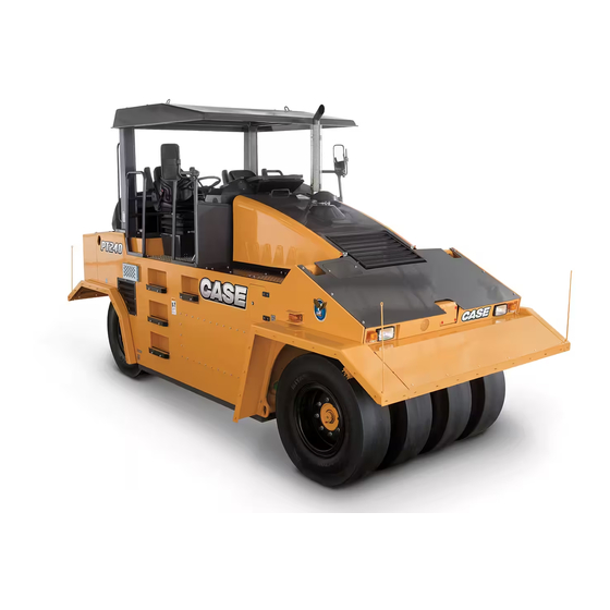
- Page 1 PT240 Tier 3 Pneumatic Line Roller SERVICE MANUAL Part number 47703681 edition English September 2015 Replaces part number 84287260A...
- Page 2 SERVICE MANUAL PT240 47703681 09/09/2015 Find manuals at https://best-manuals.com...
- Page 3 Contents INTRODUCTION Engine..................10 [10.414] Fan and drive ..............10.1 [10.400] Engine cooling system .
- Page 4 [41.200] Hydraulic control components............41.3 [41.206] Pump .
- Page 5 47703681 09/09/2015 Find manuals at https://best-manuals.com...
- Page 6 INTRODUCTION 47703681 09/09/2015 Find manuals at https://best-manuals.com...
-
Page 7: Table Of Contents
Contents INTRODUCTION Foreword - Important notice regarding equipment servicing ........3 Safety rules . -
Page 8: Foreword - Important Notice Regarding Equipment Servicing
In any case, no warranty is given or attributed on the product manufactured or marketed by the manufacturer in case of damages caused by parts and/or components not approved by the manufacturer. -
Page 9: Safety Rules
INTRODUCTION Safety rules Personal safety This is the safety alert symbol. It is used to alert you to potential personal injury hazards. Obey all safety messages that follow this symbol to avoid possible death or injury. Throughout this manual you will find the signal words DANGER, WARNING, and CAUTION followed by special in- structions. -
Page 10: Safety Rules - Personal Safety
13. When transporting on a road or highway, use accessory lights and devices for adequate warning to the opera- tors of other vehicles. In this regard, check local government regulations. Various safety lights and devices are available from your CASE CONSTRUCTION dealer. 14. Practice safety 365 days a year. -
Page 11: Safety Rules - Ecology And The Environment
Improper disposal of batteries can contaminate the soil, groundwater, and waterways. CASE CONSTRUCTION strongly recommends that you return all used batteries to a CASE CONSTRUCTION dealer, who will dispose of the used batteries or recycle the used batteries properly. -
Page 12: Safety Rules - Shop And Assembly
INTRODUCTION Safety rules - Shop and assembly O-ring seals Lubricate the O-ring seals before you insert them in the seats. This will prevent the O-ring seals from overturning and twisting, which would jeopardize sealing efficiency. Sealing compounds Apply a sealing compound on the mating surfaces when specified by the procedure. Before you apply the sealing compound, prepare the surfaces as directed by the product container. - Page 13 W0111A Special tools The special tools that CASE CONSTRUCTION suggests and illustrate in this manual have been specifically re- searched and designed for use with CASE CONSTRUCTION machines. The special tools are essential for reliable repair operations. The special tools are accurately built and rigorously tested to offer efficient and long-lasting oper- ation.
-
Page 14: Safety Rules - Hydraulic Contamination
INTRODUCTION Safety rules – Hydraulic contamination Contamination in the hydraulic system is a major cause of the malfunction of hydraulic components. Contamination is any foreign material in the hydraulic oil. Contamination can enter the hydraulic system in several ways: • When you drain the oil or disconnect any line •... -
Page 15: Personal Safety
INTRODUCTION Personal safety Wear Personal Protective Equipment (PPE) such as hard hat, eye protection, heavy gloves, hearing protection, pro- tective clothing, etc. Wear working footwear with non-slip soles. Smooth soles may slip from steps and pedals resulting in injury or incorrect operation. -
Page 16: Torque
INTRODUCTION Torque • Confirm regularly that bolted connections have not come loose. • Use torque wrenches for tightening. • If a special torque is needed, it is mentioned in the section. Thread size TIGHTENING TORQUE For screws For srews 8.8 (8G) 10.9 (10K) 10 N·m (7.4 lb ft) 14 N·m (10.3 lb ft) - Page 17 INTRODUCTION Tightening torques for cap nuts with O-ring - hoses Size wrench Thread size Hose Nominal 135 N·m (99.6 lb 115 N·m (84.8 lb 155 N·m (114.3 lb 30x2 166 N·m (122.4 lb 140 N·m (103.3 lb 192 N·m (141.6 lb 36x2 240 N·m (177.0 lb 210 N·m (154.9 lb...
- Page 18 INTRODUCTION Table for torques of plugs with flat gasket G - M Tightening torques for flanges G 1/8 15 N·m (11 lb ft) G1/4 33 N·m (24 lb ft) G 3/8 70 N·m (52 lb ft) G 1/2 90 N·m (66 lb ft) G 3/4 150 N·m (111 lb ft) 220 N·m (162 lb ft)
-
Page 19: Torque - Standard Torque Data For Hydraulics
INTRODUCTION Torque - Standard torque data for hydraulics INSTALLATION OF ADJUSTABLE FITTINGS IN STRAIGHT THREAD O RING BOSSES 1. Lubricate the O-ring by coating it with a light oil or petroleum. Install the O-ring in the groove adjacent to the metal backup washer which is assembled at the extreme end of the groove (4). - Page 20 INTRODUCTION PIPE THREAD FITTING TORQUE PIPE THREAD FITTING Torque (Maximum) Thread Size Before installing and tightening pipe fittings, clean the 1/8-27 13 N·m (10 lb ft) threads with a clean solvent or Loctite cleaner and apply 1/4-18 16 N·m (12 lb ft) sealant L ®...
-
Page 21: Basic Instructions - Shop And Assembly
Only use CNH Original Parts or CASE CONSTRUCTION Original Parts. Only genuine spare parts guarantee the same quality, duration, and safety as original parts, as they are the same parts that are assembled during standard production. Only CNH Original Parts or CASE CONSTRUCTION Original Parts can offer this guarantee. - Page 22 W0111A Special tools The special tools that CASE CONSTRUCTION suggests and illustrate in this manual have been specifically re- searched and designed for use with CASE CONSTRUCTION machines. The special tools are essential for reliable repair operations. The special tools are accurately built and rigorously tested to offer efficient and long-lasting oper- ation.
-
Page 23: Special Tools
INTRODUCTION Special tools Jigs – Engine No. 1: Handling (65-374-182) – lifting lug SS12N754 No. 2: Handling (64-373-0140) – lifting lug, screw tight- ener SS12N781 Jigs – Edge cutter No. 1: Wrench for nut KM 10 (part no. 92-655-0056) SS12N062 Jigs –... - Page 24 INTRODUCTION No. 2: Spanner to remove cover 10 (92-655-0092), (92- 655 0094) SS13A043 No. 3: Guide bush 92-644-031 SS13A044 No. 4: Checking tool (64-374-281) SS13A135 Jigs – Rear axle No. 1: (4-05103A), No. 2 (4-05102A) Installation tools (supplied as machine accessories) – to brake off the ma- chine SS12N740 47703681 09/09/2015...
- Page 25 INTRODUCTION No. 3: Installation tool (64-363-0114) – to stabilize cas- ings (1, 2) in vertical position SS13A032 No. 4: Handling tool (64-374-0111) – lifting lug by flange of differential SS13A034 No. 5: Socket driver (92-655-056) for nut KM 14 SS12N063 No.
- Page 26 INTRODUCTION Jigs – Front axle No. 1: Handling tool (65-424-121) – lifting lug to remove/ install front axle SS13A137 No. 2: Installation stand (4761 009) AXL- to remove front axle – packing material SS13A130 No. 3: Handling tool (65-424-044) – lifting lug – to handle front axle SS13A136 No.
- Page 27 INTRODUCTION No. 5: Checking tool (4851 017) AXL – for pressure test SS13A131 No. 6: Handling tool (7443 022) AXL – to handle front axle SS13A132 No. 7: Pressing tool (64-374-261) – for outer ring of bear- ing 9 SS13A133 No.
- Page 28 INTRODUCTION No. 9: Installation stand (64-374-276) SS13A134 No. 10: Pressing tool (92-631-006) - for inner ring of bear- ing 9 NOTE: When ordering the jig, use the measurement 70.00 mm (2.76 in) / 63.00 mm (2.48 in) - 200.00 mm (7.87 in).
- Page 29 INTRODUCTION No. 13: Assembly tool (92-631-006) - to press the bear- ings (ø 105.00 mm (4.13 in) / ø 85.00 mm (3.35 in) x 120.00 mm (4.72 in)) SS12N439 47703681 09/09/2015...
-
Page 30: General Specification
INTRODUCTION General specification SS12D597 Instruments and controls (1) Ignition switch In the 0 position, the machine lighting will be connected along with hand lamp socket. In the I position, other con- sumers will be connected. Spring-loaded position II is used to start the engine. The key can be removed in the 0 position only. - Page 31 INTRODUCTION (3) Tire inflation, (4) Tire deflation These are used to inflate or deflate the tires with air. NOTE: Do not switch ON both valves simultaneously to I position. (5) Transmission fluid pressure gauge The transmission fluid pressure must be within the range 12.5 - 15.5 bar (181.25 - 224.75 psi). NOTE: When pressure drops below 12.5 bar (181.25 psi), stop the machine.
- Page 32 INTRODUCTION (10) Emergency stop Press to stop the machine and engine instantly in the event of an emergency. (11) Active working position Indicates from which position (seat) the roller travel is controlled. If no indicator lamp (11) flashes when the ignition switch is turned ON, then the engine can be started.
- Page 33 INTRODUCTION Battery recharging Goes OFF when engine is started. Parking brake Indicates the brake is engaged. Engine heating Indicates the engine is warming up. Hydraulic oil filter restriction Indicates the filter element must be replaced. Idle Indicates that both travel controllers are in the neutral N idle position. Direction indicators LED lamp ON enabled workstation will light.
- Page 34 INTRODUCTION SS13F354 Instruments and controls Headlights Incl. fender lights Tail lights Hazard warning lights Hazard warning beacon (option) Differential lock (option). Parking brake Edge cutter Downward and upward (option). 47703681 09/09/2015...
- Page 35 INTRODUCTION Idle switch For engine start. Directions indicators Multifunctional display SS12N052 Multifunctional display Warning light – yellow LED lights Alarm for engine failure or minimal fuel level in tank Engine shut-off light – red LED lights Alarm for major engine malfunction Enter button Selects Menu or parameter, or conceals/displays active error code Right/up navigation button - to move cursor DOWN...
-
Page 36: General Specification
INTRODUCTION General specification NOTICE: While any company can perform the necessary maintenance or repairs on your equipment, CASE CON- STRUCTION strongly recommends that you use only CASE CONSTRUCTION dealers and products that meet given specifications. Improperly or incorrectly performed maintenance and repair voids the equipment warranty and may affect service intervals. - Page 37 460 L (121.52 US SPRINKLING TANK Water – gal) AIR-CONDITIONING Contact your dealer COMPRESSOR CNH PAG O or PAG SP20 SAE J1703 BRAKE SYSTEM SAE J1704 1.75 L (0.46 US gal) CASE AKCELA DOT 4 ISO 4925 FLUID NHTSA 116-DOT 4 47703681 09/09/2015...
- Page 38 INTRODUCTION Engine oil Engine oil has been specified as per its performance classification and viscosity classification. Performance classification under: American Petroleum Institute (API) Viscosity classification The ambient temperature and type of operations at the place where the machine will be used are decisive in determining Society of Automotive Engineers (SAE) viscosity class.
- Page 39 Always check the antifreeze concentration of the coolant with a refractometer before the winter season starts. Hydraulic oil Only hydraulic oil CASE AKCELA HY-TRAN® ULTRA™ HYDRAULIC TRANSMISSION OIL may be used for the machine’s hydraulic system. Fill the machine with hydraulic oil of cinematic viscosity 68 mm / s at 40 °C (104 °F), i.e.
- Page 40 SAE 30. Transmission fluid Final Drive Use CASE AKCELA GEAR 135 H EP 80W-90 fluid to lubricate the final drive. Speed reduction transmission Use CASE AKCELA GEAR 135 H EP 85W-140 fluid to lubricate speed reduction transmission.
-
Page 41: Product Identification (*)
This as a preview PDF file from best-manuals.com Download full PDF manual at best-manuals.com...
Need help?
Do you have a question about the PT240 and is the answer not in the manual?
Questions and answers