
Related Manuals for MG TR-EVO


Summary of Contents for MG TR-EVO
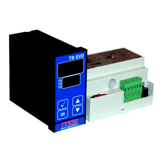
- Page 1 Draft 2 13/02/2020 TR-EVO 220-240Vac INSTRUCTIONS FOR USE INDUSTRY srl Via Casa Celeste 14 36014 Santorso (VI) Italy E-mail mg@mgonline.it...
-
Page 2: Table Of Contents
General Index Editor's notes..........................II Introduction..........................1 Warnings.............................1 Technical characteristics......................2 Description of parts........................2 Control unit........................2 Power unit..........................2 Transformer........................3 DIN bar adapter.........................3 Operation.............................3 Principles...........................3 Operating modes........................3 Installation...........................4 Assembly...........................4 Description of the connections on the power unit.............5 Signalling on power module....................8 Configuration of the switches for selection of the current ranges........8 Connections on the display unit..................9 Selection of heating element....................9 Alloys........................9... -
Page 3: Introduction
Introduction The TR-EVO temperature controller is a valid tool to adjust temperature in heating elements, without using external sensors. By taking advantage of the voltage-current characteristic, the TR-EVO manages to maintain the temperature set even in conditions of high heath loss, thereby obtaining considerable benefits compared to traditional methods used. -
Page 4: Technical Characteristics
Technical characteristics Device supply: 230 Vac (+15% / -15%) 4W max. used by controller. 115Vac option available Power supply: 230Vac with maximum distorsion of 10%. 115Vac option available Mains frequency: 47 Hz to 65 Hz whit automatic adaption to the mains frequency in this range Peak output power: 3600 VA. -
Page 5: Transformer
Transformer Technical data: -Single-phase, pulse transformer with dual safety insulation according to standards ISO/EN 61558 -Variable dimensions from mm. 122x95x108 -Variable weight starting from 4.3Kg DIN bar adapter Technical data: -Standard reference DIN EN5002250035 -Front dimensions 112x55mm. -Total depth with mounted device 155mm. -Metal an PVC made. -
Page 6: Installation
Reserve in the electrical cabinet 110mm on a DIN rail EN 50022- 50035 and insert the unit in it. 1 2 3 4 5 6 48 mm TR-EVO 8.8.8 Display unit DRILLING Cut out the panel based on the measurements given, insert... -
Page 7: Description Of The Connections On The Power Unit
The cables are used for connection to the power unit and the RS485 communication module of the PLC. Wire the system using the adequate wiring diagrams for your configuration. For example, a minimal diagram is provided below. TR-EVO 8.8.8 ≡... - Page 8 A 16A fuse with semi-rapid response should be used as the protective component. Terminals 3, 4 Output to pulse transformer primary. The transformer should be dimensioned starting with the size of the element to control, i.e. the type of alloy, width, thickness and length. (see specific section).
- Page 9 Terminals 9, 10 "IN WORK" output Opto-isolated output of sealing circuit signaling: this optical coupler is closed during the sealing cycle, and return open at the end of the cycle; see the "operating modes" section for further operating details. It can be externally configured NPN or PNP, with a maximum current which must not exceed 50mA at 24 Volts continuously.
-
Page 10: Signalling On Power Module
Current measurement input To sense the heating element current, TR-EVO has a dedicated passage where to pass one of the connecting cables between transformer and heating element. Normally the cable only makes one passage through the hole. -
Page 11: Connections On The Display Unit
Connections on the display unit 45 mm CONNECTOR FOR REMOTE CONTROL DESCRIPTION Potentiometer + output CONNETTORE CONTROLLO Control voltage input (0-10V) or potentiometer REMOTO Control voltage 0V reference or potentiometer CONNESSIONE A UNITA’ DI POTENZA Serial data terminal A EIA/TIA-485 D0- Serial interface 0V reference Serial data terminal B EiA/TIA-485 D1+ The "power unit"... -
Page 12: Hardware" Configuration
The formula: Pr=Cs×Lu× LaSp×2 enables calculation of the maximum power Pr required by the heating element, where: Cs = surface load in Watts per cm . This value determines the speed the bar heats and assumes, as seen above, a reference value of 30. Naturally, this value can be changed if higher speed is required, or less power supply is available, or power that exceeds the maximum that can be supplied by the controller. -
Page 13: Start-Up
Start-up On first start-up, the equipment will probably give an error signal. This signal is normal and depends on the fact the parameters of the heating element have not been registered yet. For the temperature controller to acquire these parameters, the Tuning procedure must be activated which should always be executed after replacing the heating element. -
Page 14: Operating Modes
Pressing the key again is displayed on greater display line and on lower display and ≡ access the equipment configuration is enabled (for information on the configuration, refer to the relevant chapter). Press the key again to display the temperature read on the heating element again. ≡... -
Page 15: System And Alarm Monitoring
Timed: temperature in this mode, when the pre-heating input is on, it activates temperature adjustment to the pre-heating temperature. Start input activates the timed heating cycle which is composed of 2 phases. The first phase (indicated with the TD led on the display) delays heating starting for the time set on the relevant timer. - Page 16 Rapid temperature change This error occurs in the tuning procedure and highlights the operation started with the heating element hot. Wait for it to cool and repeat the operation. Insufficient voltage reading; this error occurs in the tuning procedure and highlights an error in transformer connection or in its dimensioning.
-
Page 17: Configuration
Short circuit: - on the secondary circuit of the pulse transformer. - on the heating element. - on the twisted cable. Heating activated in error; this error indicates a likely fault in the power adjustment element. It can activate in the event of high inductive pulses on the power supply. Memory not valid on the temperature controller;... -
Page 18: Extended Parameters
Extended parameters The TR-evo operation is configured by adjusting another set of parameters, called extended parameters which can be accessed with the following procedure: To access the extended configuration parameters, bring the bottom display to value... - Page 19 0-10V voltage connected instead of the potentiometer. input 0-5V with potentiometer input 0-10V code 17 Alloy used in heater. Indicates to the TR-evo which material the heating element is made of, to allow the correct temperature indication. = Nichrome40 = AISI 316...
-
Page 20: Maintenance
= 4800b/s = 9600b/s code 22 Device bus addres. Selects the number of peripheral devices that the TR-evo assumes in the communications bus, its function is to allow multiple devices to connect to the same communications port without interfering with each other. Device address 58 is reserved and must not be used on the bus that contains TR-evo devices. -
Page 21: Warranty
Warranty M.G. industry srl guarantees its product, identified via a manufacturing code or by a brand name, is free of material and manufacturing defects which would mean it does not conform to the technical specifications indicated, and is committed for 12 months, starting from delivery date, to repairing or replacing the faulty part, component, equipment or part of it free of charge, returned to the manufacturer, unless the fault or malfunction is due to: a) poor installation, even if conducted by qualified staff;... -
Page 23: Appendix
Appendix System dimensioning To help you choose the components of your system, please compile the following module and send it to us. Based on the data provided by you, we can prepare an application diagram. Company: Manager: Telephone E-mail Power supply voltage Vac frequency Maximum power available Watt... - Page 24 Heating element connection Number of seals to simultaneously execute with connection: q single q parallel q series q other type of connection (attach application diagram) Cooling q no q air q water Timed management of sealing q no q on machine q on temperature controller Desired user interface q numerical display and potentiometer...
Need help?
Do you have a question about the TR-EVO and is the answer not in the manual?
Questions and answers