Table of Contents
Advertisement
Advertisement
Table of Contents

Related Manuals for Keysight Technologies U2000 Series


Summary of Contents for Keysight Technologies U2000 Series
- Page 1 Keysight U2000 Series USB Power Sensors Operating and Service Guide...
-
Page 4: Notices
FAR 12.211 (Technical Data) and 12.212 (Computer Software) and, for the Department of Defense, DFARS 252.227-7015 (Technical Data - Commercial Items) and DFARS 227.7202-3 (Rights in Commercial Computer Software or Com- puter Software Documentation). U2000 Series Operating and Service Guide... -
Page 5: Certification
Certification Keysight Technologies certifies that this product met its published specifications at the time of shipment from the factory. Keysight Technologies further certifies that its calibration measurements are traceable to the United States National Institute of Standard and Technology, to the extent allowed by the Institute’s calibration facility, and to the calibration facilities of other International Standard Organization members. -
Page 6: Safety Summary
Failure to comply with these precautions or with specific warnings elsewhere in this manual violates safety standards of design, manufacture, and intended use of the instrument. Keysight Technologies assumes no liability for the customer’s failure to comply with these requirements. Safety Notices A WARNING notice denotes a hazard. -
Page 7: Safety Symbols
Earth (ground) terminal manual for specific Warning or Caution information). Protective conductor terminal Caution, hot surface. Frame or chassis terminal Out position of a bi-stable push control. Equipotentiality In position of a bi-stable push control. U2000 Series Operating and Service Guide... -
Page 8: Regulatory Markings
The affixed product label indicates that you must not discard this electri- cal/electronic product in domestic household waste. ICES/NMB-001 indicates that this ISM device complies with Canadian ICES-001. ICES/NMB - 001 Cet appareil ISM est confomre à la norme NMB-001 du Canada U2000 Series Operating and Service Guide... -
Page 9: Waste Electrical And Electronic Equipment (Weee) Directive 20002/96/Ec
“Monitoring and Control Instrument” product. The affixed product label is shown as below: Do not dispose in domestic household waste To return this unwanted instrument, contact your nearest Keysight office, or visit www.keysight.com/environment/product for more information. VIII U2000 Series Operating and Service Guide... -
Page 10: General Safety Information
Keysight Technologies assumes no liability for the customer’s failure to comply with these requirements. BEFORE CONNECTING THE POWER SENSOR TO OTHER INSTRUMENTS... -
Page 11: Environmental Conditions
Non-operating up to 4,600 metres (15, 000 feet) Pollution Degree 2 The Keysight U2000 Series USB power sensors comply with the following safety C A U T I O N and EMC requirements: • IEC 61010-1:2001 / EN 61010-1:2001 (2nd edition) •... - Page 12 Keysight Web site. You can search the DoC by its product model or description at the Web address below. http://regulations.products.keysight.com/DoC/search.htm If you are unable to search for the respective DoC, please contact your N O T E local Keysight representative. U2000 Series Operating and Service Guide...
- Page 13 THIS PAGE HAS BEEN INTENTIONALLY LEFT BLANK. U2000 Series Operating and Service Guide...
-
Page 14: Table Of Contents
Introduction 2 Power Sensor Overview 3 • LED Indicator Guide 4 Principles of Operation 6 The U2000 Series USB Power Sensors in Detail 9 Initial Inspection 11 • Package Contents Checklist 11 Hardware Installation and Configuration 12 • System Requirements 12 •... - Page 15 • Frequency and Power Ranges 38 • Connector Type 38 • Maximum SWR (25 °C ±10 °C) 39 • SWR Plots for U2000 Series USB Power Sensors 40 • Maximum SWR (0 °C to 55 °C) 45 • Maximum Power 47 •...
- Page 16 Service 76 Troubleshooting 76 Repairing a Defective Sensor 76 Disassembly and Reassembly Procedure 77 Attenuator Disassembly and Reassembly Procedure for U2000B and U2001B 79 Appendix Appendix A: Zero Set, Zero Drift, and Measurement Noise 82 U2000 Series Operating and Service Guide...
- Page 17 THIS PAGE HAS BEEN INTENTIONALLY LEFT BLANK. U2000 Series Operating and Service Guide...
- Page 18 Figure 3-12 Typical power accuracy at 25 °C for U2000/1/2H models Figure 3-13 Settling time with auto filter, default resolution, and a 10 dB decreasing power step (not across the switching point) 60 U2000 Series Operating and Service Guide XVII...
- Page 19 THIS PAGE HAS BEEN INTENTIONALLY LEFT BLANK. XVIII U2000 Series Operating and Service Guide...
- Page 20 Table 4-10 Replaceable Parts 75 Table 4-11 Disassembly Procedure 77 Table 4-12 Attenuator Disassembly Procedure 79 Table 4-13 Attenuator Reassembly Procedure 80 Table A-1 Zero Set, Zero Drift, and Measurement Noise for Average only Mode 82 U2000 Series Operating and Service Guide...
- Page 21 THIS PAGE HAS BEEN INTENTIONALLY LEFT BLANK. U2000 Series Operating and Service Guide...
-
Page 22: Getting Started
Hardware Installation and Configuration 12 Checking the Power Sensor Firmware 19 This chapter introduces the Keysight U2000 Series USB power sensor with detailed information on the principles of operation, initial inspection, hardware installation and configuration, and a brief introduction of the... -
Page 23: Introduction
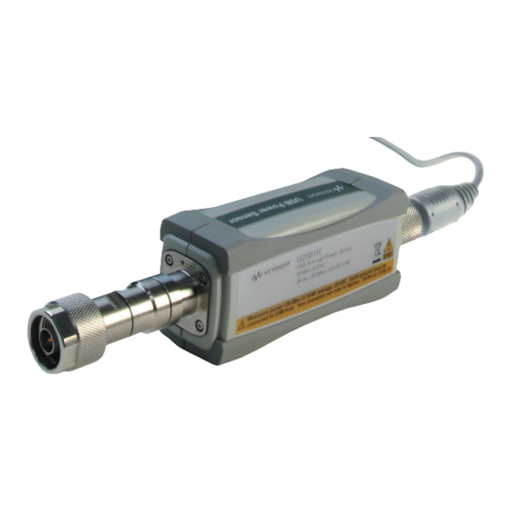
USB connectivity to a PC or laptop, thus eliminating the need for a separate conventional power meter. The power sensors also compatible with some selected USB- based instruments from Keysight. The figure below shows the Keysight U2000 Series USB power sensors family. U2000A... -
Page 24: Power Sensor Overview
DO NOT remove or disassemble the gold connector on the U2002H. This is a fixed body C A U T I O N part of the U2002H. Removing this connector will make the sensor defective. U2000 Series Operating and Service Guide... -
Page 25: Led Indicator Guide
Example of error cause: 1 SCPI command syntax error 2 Invalid Zero AMBER Zeroing is in progress. Sending SCPI commands during the zeroing process will cause error. This will cause the LED indicator to turn RED. U2000 Series Operating and Service Guide... -
Page 26: Figure 1-1 Led Indicator Sequence During Power-Up
Getting Started Power Up HW/OS Error USB Enumeration GREEN Blinking Blinking Self-test fail Self-test GREEN Blinking Blinking Internal Zeroing - Default AMBER Read Figure 1-1 LED indicator sequence during power-up U2000 Series Operating and Service Guide... -
Page 27: Principles Of Operation
The new U2000 Series includes all the signal conditioning and analog- to- digital formatting functions that have been in use for several years. Thus, you can be assured that the U2000 Series USB power sensor will deliver highly predictable results. - Page 28 Figure 1- 3. The trigger input port which is based on TTL enables the sensor to synchronize with events. The U2000 Series supports high data rate transfer of 480 Mb/s through the Universal Serial Bus (USB) connectivity which is USB- TMC compliance.
-
Page 29: Figure 1-2 Block Diagram Of The Rf/Microwave Usb Power Sensor
Getting Started U2000 Series Operating and Service Guide... -
Page 30: The U2000 Series Usb Power Sensors In Detail
Specialized modulation sensors are able to provide accurate measurements but are limited by the bandwidth. The U2000 Series USB power sensor are true average, wide dynamic range RF/microwave power sensors. They are based on a dual sensor diode pair/ attenuator/diode pair as proposed by Szente et. - Page 31 CDMA, W- CDMA, and digital television formats. 1 November 1986 Hewlett-Packard Journal pages 14-2, “Diode Integrated Circuits for Milimeter-Wave Applications. 2 Refer to“Maximum Power” on page 47 for maximum power handling specifications. U2000 Series Operating and Service Guide...
-
Page 32: Initial Inspection
Package Contents Checklist Inspect and verify the following items for the standard purchase of the U2000 Series USB power sensor . If there are missing items, contact the nearest Keysight Sales Office. Trigger cable BNC Male to SMB female 50 Ω, 1.5 m •... -
Page 33: Hardware Installation And Configuration
Getting Started Hardware Installation and Configuration System Requirements Prior to using the U2000 Series USB power sensor , please ensure that the following minimum requirements are met: • PC or any device that has USB host capability • Keysight IO Libraries Suite 15.5 or higher had been installed. Users are encouraged to obtain the latest version of Keysight Libraries Suite for better performance. -
Page 34: Installing Your U2000 Series Usb Power Sensor
N1918A Power Analysis Manager. Follow the instructions below to install and configure the U2000 Series. 1 Connect your U2000 Series USB power sensor to the PC using the USB cable provided. Connect the cable’s mini- B plug to your power sensor... -
Page 35: Figure 1-5 Found New Hardware Wizard Driver Installation
1 Go to Start > Control Panel and double-click System. 2 Select Hardware tab, on the Drivers panel click Driver Signing and the Driver Signing Options dialog box will appear. 3 Select Ignore to disable the warning message. U2000 Series Operating and Service Guide... -
Page 36: Figure 1-7 Completing Hardware Driver Installations
Each time a USB device is plugged in, this dialog will be shown. To configure or disable this dialog, select an options in the Show this dialog panel and click OK. Figure 1-8 USB device alias configuration U2000 Series Operating and Service Guide... -
Page 37: Verifying Your Connected Power Sensor
PC and right- click. A context menu will appear and select Send Command To This Instrument and the Keysight Interactive IO dialog box will appear as shown below. Figure 1-10 Keysight Interactive IO dialog box U2000 Series Operating and Service Guide... -
Page 38: Figure 1-11 Identification Of Your Connected Power Sensor Displayed
Instrument Session History panel as shown in the following figure. Figure 1-11 Identification of your connected power sensor displayed 5 This verify that your U2000 Series USB power sensor has been connected and properly installed on your PC. U2000 Series Operating and Service Guide... -
Page 39: Configuring Your Power Sensor Via Power Analysis Manager
Power Analysis Manager. The reminder message will appear under two conditions: a You have not set any calibration due date for your U2000 Series. The reminder prompts you to set your calibration due date. b Your calibration date is due and the reminder prompts you to send your U2000 Series for calibration. -
Page 40: Checking The Power Sensor Firmware
By using the Keysight IO Libraries Suite version 15.5 or higher, you can check the model code, serial number, firmware revision, and USB address. The VISA address is the USB address (see below). Figure 1-12 Keysight IO Libraries Suite U2000 Series Operating and Service Guide... -
Page 41: Keysight N1918A Power Analysis Manager
Figure 1-13 Power Analysis Manager Instrument Properties panel It is advisable to set the calibration due date. Refer to page 18 for more details. Figure 1-14 Calibration due date display U2000 Series Operating and Service Guide... -
Page 42: Operating Information
Keysight U2000 Series USB Power Sensors Operating and Service Guide Operating Information Measurement Mode 22 Power Sensor Configuration Settings 25 Measurement Accuracy and Speed 27 Internal and External Zeroing 30 Power Sweep and Frequency Sweep 32 Step Detection 33 Pulse Power Measurement in Average only Mode 34 This chapter describes some general operating information of the U2000 Series USB power sensor . -
Page 43: Measurement Mode
(internal trigger) or controlled externally via TTL input (external trigger). Trace Display The U2000 Series USB power sensor can also be configured to display measurement results in trace format using SCPI commands or the N1918A Power Analysis Manager when the power sensors are set to normal mode. -
Page 44: Figure 2-1 Example Of Trace Graph Display For Gsm Signal
Operating Information Figure 2-1 Example of trace graph display for GSM signal U2000 Series Operating and Service Guide... -
Page 45: Figure 2-2 Measurement Gate
40 µs (fall time) offset from the pulse falling edge to achieve higher accuracy measurements. Samples collected during range settling time are discarded. Thus, fewer samples are used for generating a measurement. U2000 Series Operating and Service Guide... -
Page 46: Power Sensor Configuration Settings
Power Sensor Configuration Settings The auto- averaging settings shown in Figure 2- 3 are automatically configured when the U2000 Series USB power sensors are connected. Averaging settings can also be manually configured. N O T E Figure 2- 3, the dotted- line arrow indicates the internal range based on the internal circuitry of the power sensor. -
Page 47: Figure 2-3 Auto-Averaging Settings
–45 dBm –35 dBm 128 1024 1024 1024 –25 dBm –55 dBm –45 dBm 512 1024 1024 1024 –30 dBm –60 dBm –50 dBm Minimum Sensor Power Within a Range Figure 2-3 Auto-averaging settings U2000 Series Operating and Service Guide... -
Page 48: Measurement Accuracy And Speed
Operating Information Measurement Accuracy and Speed With U2000 Series USB power sensor , the range can be set either automatically or manually. Use auto- ranging when you are not sure of the power level you are about to measure. The DC coupling of the U2004A USB power sensor input allows excellent low frequency coverage. -
Page 49: Measurement Considerations
However, the peak amplitude of –6 dBm is beyond the specified square law response range of the low power path diodes. The high power path (–7 dBm to +20 dBm) should be used to ensure a more accurate U2000 Series Operating and Service Guide... - Page 50 You can achieve best accuracy by selecting the high power path or achieve best speed by selecting the low power path. U2000 Series Operating and Service Guide...
-
Page 51: Internal And External Zeroing
Zeroing a power sensor is performed in order to reduce zero measurement offset and noise impact to improve the accuracy of RF power measurement. The U2000 Series USB power sensor have two types of zeroing; internal zeroing and external zeroing. -
Page 52: Figure 2-4 Select Either Int Or Ext From The Zero Type Option
Operating Information Figure 2-4 Select either INT or EXT from the Zero Type option U2000 Series Operating and Service Guide... -
Page 53: Power Sweep And Frequency Sweep
Power Sweep and Frequency Sweep The frequency sweep and power sweep features provide measurement automation between the U2000 Series USB power sensor and the signal source. This feature reduces the communication path and improves test time by eliminating the need of PC- instrument communication. -
Page 54: Step Detection
Step detection can be set in both manual and automatic filter modes. Refer to the U2000 Series Programming Guide for more details on how to enable or disable the step detection. -
Page 55: Pulse Power Measurement In Average Only Mode
It is recommended to disable the step detection and set the average count to ≥256. The U2000 Series USB power sensor are designed to perform average power measurements over dynamic range of –60 dBm to +44 dBm. The supported power range for each sensor model is shown as... -
Page 56: Specifications And Characteristics
Keysight U2000 Series USB Power Sensors Operating and Service Guide Specifications and Characteristics Introduction 36 Specifications 38 General Characteristics 67 This chapter describes the specifications and characteristics of your U2000 Series USB power sensor . -
Page 57: Introduction
These specifications are valid after a 30- minute warm- up period. The dynamic range of the U2000 Series USB power sensors is –60 dBm to +44 dBm and the range is divided into two independent measurement paths — a low power path and a high power path, as shown below:... - Page 58 These specifications are referred to as typical. • Typical plots are derived from a population mean from production testing. Plot shown may vary from unit to unit and is not warranted. For warranted specifications, please refer to the individual tables. U2000 Series Operating and Service Guide...
-
Page 59: Specifications
10 MHz to 6 GHz Connector Type Model Connector Type Impedance 50 Ω U2000/1/4A N-Type (m) 50 Ω U2002A 3.5 mm (m) 50 Ω U2000/1H N-Type (m) 50 Ω U2002H 3.5 mm (m) 50 Ω U2000/1B N-Type (m) U2000 Series Operating and Service Guide... -
Page 60: Maximum Swr (25 °C ±10 °C)
12.4 GHz to 18 GHz 1.24 10 MHz to 2 GHz 1.12 U2001B 2 GHz to 6 GHz 1.17 10 MHz to 8 GHz 1.15 U2000H 8 GHz to 12.4 GHz 1.25 12.4 GHz to 18 GHz 1.28 U2000 Series Operating and Service Guide... -
Page 61: Swr Plots For U2000 Series Usb Power Sensors
8 GHz to 12.4 GHz 1.25 U2002H 12.4 GHz to 18 GHz 1.28 18 GHz to 24 GHz 1.30 SWR Plots for U2000 Series USB Power Sensors Figure 3-1 U2000A typical SWR (25 °C ±10 °C) U2000 Series Operating and Service Guide... -
Page 62: Figure 3-2 U2001A Typical Swr (25 °C ±10 °C)
Specifications and Characteristics Figure 3-2 U2001A Typical SWR (25 °C ±10 °C) Figure 3-3 U2002A Typical SWR (25 °C ±10 °C) U2000 Series Operating and Service Guide... -
Page 63: Figure 3-4 U2004A Typical Swr (25 °C ±10 °C)
Specifications and Characteristics Figure 3-4 U2004A Typical SWR (25 °C ±10 °C) Figure 3-5 U2000H Typical SWR (25 °C ±10 °C) U2000 Series Operating and Service Guide... -
Page 64: Figure 3-6 U2001H Typical Swr (25 °C ±10 °C)
Specifications and Characteristics Figure 3-6 U2001H Typical SWR (25 °C ±10 °C) Figure 3-7 U2002H Typical SWR (25 °C ±10 °C) U2000 Series Operating and Service Guide... -
Page 65: Figure 3-8 U2000B Typical Swr (25 °C ±10 °C)
Specifications and Characteristics Figure 3-8 U2000B typical SWR (25 °C ±10 °C) Figure 3-9 U2001B typical SWR (25 °C ±10 °C) U2000 Series Operating and Service Guide... -
Page 66: Maximum Swr (0 °C To 55 °C)
2 GHz to 6 GHz 1.20 10 MHz to 2 GHz 1.14 U2000B 2 GHz to 12.4 GHz 1.18 12.4 GHz to 18 GHz 1.25 10 MHz to 2 GHz 1.14 U2001B 2 GHz to 6 GHz 1.18 U2000 Series Operating and Service Guide... - Page 67 12.4 GHz to 18 GHz 1.29 U2001H 10 MHz to 6 GHz 1.17 50 MHz to 8 GHz 1.17 8 GHz to 12.4 GHz 1.26 U2002H 12.4 GHz to 18 GHz 1.29 18 GHz to 24 GHz 1.31 U2000 Series Operating and Service Guide...
-
Page 68: Maximum Power
Users are advised to use suitable external DC block for the DC component removal. DC voltages in excess of the maximum value (5 V) can damage the sensing diode. U2000 Series Operating and Service Guide... -
Page 69: Power Accuracy
For overall accuracy, refer to the measurement uncertainty calculator which is available on the Keysight Technologies Web site. 3 It is strongly advisable to perform external zeroing on the U2000 Series USB power sensor for power measurement level below –30 dBm (U2000/1/2A), –20 dBm (U2000/1/2H), and 0 dBm (U2000/1B) for accurate measurements. -
Page 70: Figure 3-10 Typical Power Accuracy At 25 °C For U2000/1/2/4A Models
Specifications and Characteristics Power Accuracy Plots (Average only Mode) 1, 2 Figure 3-10 Typical power accuracy at for U2000/1/2/4A models 25 °C 1, 2 Figure 3-11 Typical power accuracy at for U2000/1B models 25 °C U2000 Series Operating and Service Guide... -
Page 71: Figure 3-12 Typical Power Accuracy At 25 °C For U2000/1/2H Models
(zero set, drift, and noise). Refer to Keysight Fundamentals of RF and Microwave Power Measurements (Part 3) Power Measurement Uncertainty per International Guide (Application Note 1449-3), 5988-9215EN for more information on measurement uncertainty. 2 After zeroing, 30 minutes of power-on warm-up, and 1024 averages. U2000 Series Operating and Service Guide... -
Page 72: Switching Point
Specifications and Characteristics Switching Point The U2000 Series USB power sensor have two measurement paths: a low power path and a high power path as shown in Table 3- Table 3-3 Switching point Sensor Low Power Path High Power Path... - Page 73 The high power path remains selected until approximately +22.5 dBm has been reached. As the power level decreases below +22.5 dBm, the low power path will be selected. U2000 Series Operating and Service Guide...
-
Page 74: Zero Set, Zero Drift, And Measurement Noise
2.5 dBm to 8 dBm 500 nW 6.5 µW ±40 µW ±30 µW 6 dBm to 25 dBm 5 µW 10 µW ±60 µW ±60 µW 20 dBm to 30 dBm 20 µW 100 µW U2000 Series Operating and Service Guide... - Page 75 The Zero Set, Zero Drift, and Measurement Noise specifications are only applicable to N O T E U2000 Series USB power sensors with serial prefix as shown below: U2000A Serial prefix MY480/SG480 and above U2001A Serial prefix MY481/SG481 and above...
-
Page 76: Table 3-4 Noise Multiplier For Average Only Mode
0.91 0.78 0.53 0.34 0.29 0.20 (x2 Speed) Example: U2000A power sensor, –60 dBm to –35 dBm, number of averages = 4, normal speed. Measurement noise calculation: 1 nW x 1.7 = 1.7 nW U2000 Series Operating and Service Guide... - Page 77 230 µW 550 µW 6 dBm to 25 dBm 440 µW 300 µW 300 µW 260 µW 850 µW 20 dBm to 30 dBm 3.9 mW 2.8 mW 1.1 mW 2.8 mW 5.5 mW U2000 Series Operating and Service Guide...
- Page 78 Number of averages If the noise value obtained from Equation 1 or 2 is lower than the measurement noise N O T E specification, use the value as specified in the measurement noise table. U2000 Series Operating and Service Guide...
- Page 79 ------------------------------------------------ - 85µW 1.123µW ⁄ 1.36 ms 0.68µs The calculated measurement noise (1.123 µW) is lower than the measurement noise specification (21 µW). In this case, the measurement noise would be 21 µW. U2000 Series Operating and Service Guide...
-
Page 80: Settling Time
Table 3-5 Settling Time for Normal and x2 Speed Number of Averages 1,024 Settling Time (s) 0.045 0.09 0.17 0.34 0.66 10.4 20.9 41.9 (Normal Speed) Settling Time (s) 0.042 0.05 0.09 0.17 0.34 0.66 10.4 20.9 (x2 Speed) U2000 Series Operating and Service Guide... -
Page 81: Figure 3-13 Settling Time With Auto Filter, Default Resolution, And A 10 Db Decreasing Power Step (Not Across The Switching Point)
20 dBm 40 dBm 42 s 24 s Minimum sensor power within a range Figure 3-13 Settling time with auto filter, default resolution, and a 10 dB decreasing power step (not across the switching point) U2000 Series Operating and Service Guide... -
Page 82: Calibration Factor And Reflection Coefficient
– Typical uncertainties of the CF data are listed in the following tables. As the U2000 Series USB power sensors have two independent measurement paths (high and low power paths), there is only one set of CF data used for both high and low power paths for each sensor. The uncertainty analysis for the calibration of the sensors was done in accordance with the ISO Guide. -
Page 83: Cal Factor Uncertainty
Typical CF Uncertainty (25 °C ±10 °C) 50 MHz to 2 GHz 2.0% 2 GHz to 14 GHz 2.5% 14 GHz to 16 GHz 2.7% 16 GHz to 18 GHz 2.7% 18 GHz to 24 GHz 3.0% U2000 Series Operating and Service Guide... - Page 84 1.8% 2 GHz to 6 GHz 2.0% U2000H Frequency Typical CF Uncertainty (25 °C ±10 °C) 10 MHz to 8 GHz 2.0% 8 GHz to 12.4 GHz 2.0% 12.4 GHz to 18 GHz 2.2% U2000 Series Operating and Service Guide...
- Page 85 2.0% U2002H Frequency Typical CF Uncertainty (25 °C ±10 °C) 50 MHz to 8 GHz 2.5% 8 GHz to 12.4 GHz 2.5% 12.4 GHz to 18 GHz 2.7% 18 GHz to 24 GHz 3.0% U2000 Series Operating and Service Guide...
-
Page 86: Trigger
11 µs ±2 µs Trigger Delay Range –0.15 s to +0.15 s Resolution 1 µs Trigger hold-off Range 1 µs to 400 ms Resolution 1 µs Trigger Hysteresis Range 0 dB to +3 dB Resolution 0.1 dB U2000 Series Operating and Service Guide... -
Page 87: Normal Mode Key Specifications And Characteristics
Maximum capture length 150 ms Maximum pulse repetition rate 150 kHz Dynamic range U2000/1/2A: –30 dBm to +20 dBm U2000/1/2H: –20 dBm to +30 dBm U2000/1B: 0 dBm to +44 dBm 1 Not applicable for U2004A U2000 Series Operating and Service Guide... -
Page 88: General Characteristics
The sensor should be stored in a clean, dry Environment environment Temperature –30 °C to +70 °C (non-operating) Non-operating up to 90% at 65 °C Relative Humidity (non-condensing) Altitude Non-operating up to 4,600 metres (15,000 feet) USB Standard USB Speed Hi-Speed 2.0 U2000 Series Operating and Service Guide... - Page 89 Specifications and Characteristics THIS PAGE HAS BEEN INTENTIONALLY LEFT BLANK. U2000 Series Operating and Service Guide...
-
Page 90: Service
Keysight U2000 Series USB Power Sensors Operating and Service Guide Service General Information 70 Performance Test 71 Replaceable Parts 74 Service 76 Troubleshooting 76 This chapter describes the performance test and provides information on replaceable parts as well as on service details. -
Page 91: General Information
This chapter contains information about general maintenance, performance tests, troubleshooting and the repair of U2000 Series USB power sensors. Cleaning Use a clean, damp cloth to clean the body of the U2000 Series USB power sensors. Connector Cleaning The RF connector beads deteriorate when contacted with hydrocarbon compounds such as C A U T I O N acetone, trichloroethylene, carbon tetrachloride, and benzene. -
Page 92: Performance Test
The test system used must not exceed the system Rho uncertainties shown in the following tables when testing the U2000 Series USB power sensors. Table 4-1 Power Sensor SWR and Reflection Coefficient for the U2000A... -
Page 93: Table 4-3 Power Sensor Swr And Reflection Coefficient For The U2002A
Table 4-5 Power Sensor SWR and Reflection Coefficient for the U2000H Frequency Actual Maximum Measurement 10 MHz to 8 GHz 0.070 1.15 8 GHz to 12.4 GHz 0.111 1.25 12.4 GHz to 18 GHz 0.123 1.28 U2000 Series Operating and Service Guide... -
Page 94: Table 4-6 Power Sensor Swr And Reflection Coefficient For The U2001H
12.4 GHz to 18 GHz 0.107 1.24 Table 4-9 Power Sensor SWR and Reflection Coefficient for the U2001B Frequency Actual Maximum Measurement 10 MHz to 2 GHz 0.057 1.12 2 GHz to 6 GHz 0.078 1.17 U2000 Series Operating and Service Guide... -
Page 95: Replaceable Parts
N O T E California. Ask your nearest Keysight office for information and forms for the “Direct Mail Order System.” Also your nearest Keysight office can supply toll free telephone numbers for ordering parts and supplies. U2000 Series Operating and Service Guide... -
Page 96: Table 4-10 Replaceable Parts
U2000-60010 U2001H replacement module U2001H 5190-1711 Top label for U2001H U2000-60011 U2002H replacement module U2002H 5190-1712 Top label for U2002H 5190-0061 Middle label 5190-0060 Bottom label All models U2000-20001 Top cover U2000-20003 Bottom cover U2000 Series Operating and Service Guide... -
Page 97: Service
Troubleshooting The U2000 Series USB power sensors represent a combination of a power meter and power sensor in one unit. If the LED is red and blinking, it indicates that there is a hardware error or operating system (OS) error in the power sensor. -
Page 98: Disassembly And Reassembly Procedure
Table 4-11 Disassembly Procedure 1 Remove the top label. 2 Loosen three screws by using M2 to remove the housing. 3 Replace the defective sensor module with a new sensor module. Please refer to Table 4- U2000 Series Operating and Service Guide... - Page 99 Service Reassembly Procedure Tools required for reassembly: Tools Purpose Torque value M2 Torx To fit the housing 3.98 lbs.in Reassembly instructions: The reassembly procedures are simply the reversal of the disassembly procedure. U2000 Series Operating and Service Guide...
-
Page 100: Attenuator Disassembly And Reassembly Procedure For U2000B And U2001B
U2001B will void the calibration. Table 4-12 Attenuator Disassembly Procedure 1 Loosen the connector using the torque wrench. 2 After that clean the connector’s threads with IPA. Ensure that the crystallized loctite is cleaned properly. U2000 Series Operating and Service Guide... -
Page 101: Table 4-13 Attenuator Reassembly Procedure
To tighten the attenuator 12 lbs.in Table 4-13 Attenuator Reassembly Procedure 1 Apply one drop of loctite on the first, second, and third threads of the connector. 2 Tighten the connector using the torque wrench. U2000 Series Operating and Service Guide... -
Page 102: Appendix
Keysight U2000 Series USB Power Sensors Operating and Service Guide Appendix Appendix A: Zero Set, Zero Drift, and Measurement Noise 82... -
Page 103: Appendix A: Zero Set, Zero Drift, And Measurement Noise
2 Within one hour after zero set, at a constant temperature, after 24-hour warm-up of the power sensor. 3 The number of averages at 16 for Normal speed, measured over one minute interval and two standard deviations. U2000 Series Operating and Service Guide... - Page 104 www.keysight.com Contact us To obtain service, warranty, or technical sup- port assistance, contact us at the following phone numbers: United States: (tel) 800 829 4444 (fax) 800 829 4433 Canada: (tel) 877 894 4414 (fax) 800 746 4866 China: (tel) 800 810 0189 (fax) 800 820 2816 Europe: (tel) 31 20 547 2111...
- Page 105 This information is subject to change without notice. © Keysight Technologies 2007 - 2015 Edition 12, June 26, 2015 *U2000-90405* U2000-90405 www.keysight.com...
Need help?
Do you have a question about the U2000 Series and is the answer not in the manual?
Questions and answers